Cub-Cadet Domestic 5000 Series Compact Tractor Service Manual
What's Included?
Lifetime Access
Fast Download Speeds
Online & Offline Access
Access PDF Contents & Bookmarks
Full Search Facility
Print one or all pages of your manual
Service Manual Domestic Series 5000 Compact Tractor MTD Products Inc. - Product Training and Education Department FORM NUMBER - 769-01633 12/2004 NOTE: These materials are prepared for use by trained technicians who are experienced in the service and repair of equipment of the kind described in this publication, and are not intended for use by untrained or inexperienced individuals. Such individuals should seek the assistance of an authorized service technician or dealer. Read, understand, and follow all directions when working on this equip- ment. This includes the contents of the Operators Manual, which came with your equipment. No liability can be accepted for any inac- curacies or omission in this publication, although every care has been take to make it as complete and accurate as possible. The right is reserved to make changes at any time to this document without prior notice and without incurring an obligation to make such changes to previously published documents. All information contained in this publication is based on product information available at the time of publication. Photographs and illustrations used in this publication are for reference use only and may not depict actual model and component parts.
I CHAPTER 1 - Hydraulics Standard Hydraulic Systems on the Domestic Series 5000: Orientation ......................................1 Hydrostatic Drive: Basic Operation ...............................................................................................4 External Checks ............................................................................................................................6 Best Practices: Hydraulic Systems ................................................................................................8 Flow and Pressure Tests: Hydrostatic Drive .................................................................................8 Auxiliary Pump ............................................................................................................................12 Steering Pump and Cylinder .......................................................................................................14 Hydraulic Lift Cylinder and Control Valve ....................................................................................18 Loader Valve ...............................................................................................................................22 Component Breakdown: Auxiliary Pump .....................................................................................25 Component Breakdown: Steering Unit ........................................................................................26 CHAPTER 2 - MFD About This Section: .....................................................................................................................31 Identifying the MFD: ....................................................................................................................31 Domestic Series 5000 MFD ........................................................................................................31 MFD Removal: Preparation .........................................................................................................33 Removal ......................................................................................................................................34 MFD Installation ..........................................................................................................................36 In-Frame Repairs: Drop Axle Service ..........................................................................................37 In Frame Repairs: Drop Axle Cover ............................................................................................38 In-Frame Repairs: Drop-Axle Removal .......................................................................................40 Bench Repairs: Drop Axle and Kingpin Housing Assemblies .....................................................42 Bench Repair: Axles and Differential. ..........................................................................................46 Torque Specifications ..................................................................................................................60 CHAPTER 3 - Rear Axle Reason for Change: ....................................................................................................................61 Preparation: .................................................................................................................................61 Axle Assembly .............................................................................................................................63 Install the New Axle. ....................................................................................................................64 CHAPTER 4 - Deck Adapter Kit - 190-830-100 65 About This Section: ..................................................................................................................... 65 Preparation and Brackets: ...........................................................................................................65 Lift Shaft and Arms: .....................................................................................................................66 Hanger to Deck Connections ......................................................................................................67 Mating the Deck to the Tractor ....................................................................................................68 CHAPTER 5 - Dash and Steering Pump About This Section: .....................................................................................................................71 Dash Panel Removal ...................................................................................................................71 The Dash Panel ...........................................................................................................................75 Steering Shaft and Pump: Sauer .................................................................................................77 Steering Shaft and Pump: Ross ..................................................................................................79 TABLE OF CONTENTS
II CHAPTER 6 - Electrical System Similarities and Differences ..........................................................................................................81 Components .................................................................................................................................82 Electric Clutch and Fuel Pump .....................................................................................................90
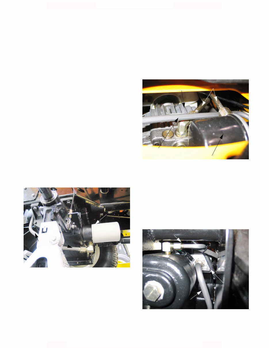
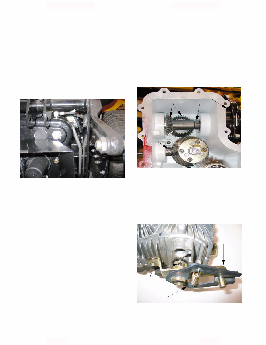
Domestic Series 5000 Hydraulics 1 1. STANDARD HYDRAULIC SYSTEMS ON THE DOMESTIC SERIES 5000: ORIENTATION NOTE: Subsections 1 and 2 of the Domestic Series 5000 Hydraulics portion of this manual provide a basic orientation to the system. Sub- section 3 and those that follow it contain specific test procedures. NOTE: Hydraulic diagrams are contained in an appendix to this section. 1.1. The transmission housing acts as a reservoir for all of the hydraulic systems on the tractor: hydro- static drive pump, hydrostatic steering system, lift cylinder, and accessories. 1.2. Fluid: the transmission and hydraulic system are filled with 5.0 gallons (19.0 L) of Cub Cadet Hydraulic Drive System Fluid Plus (P/N: 737- 3120 1Qt., 737-3121 1Gal.). 1.3. Filtration: The hydraulic system filter (P/N:723- 0405) is located on a boss on the front surface of the transmission housing, adjacent to the mid- mount, 2000 R.P.M. P.T.O. shaft. See Figure 1.3. Figure 1.3 system filter Hydraulic Suction tube (feeds aux- iliary pump) 1.4. The hydrostatic drive filter (P/N: BS-492932S) is located on the return manifold, atop the trans- mission. It is accessible through the opening beneath the seat. See Figure 1.4. NOTE: Other than sharing a reservoir, the hydrostatic drive operates independently of the rest of the hydraulic system. 1.5. The hydrostatic drive is a Hydrogear model BDU-21L-400. It relies on the auxiliary pump to produce charge pressure. The auxiliary pump draws hydraulic fluid up the suction pipe from the base of the transmission housing. See Figure 1.5. Figure 1.4 Hydrostatic drive filter Charge pressure tube from aux. pump to filter Charge pressure tube from filter to hydrostat BDU-21L-400 Figure 1.5 Suction tube Auxiliary pump Return tube Domestic Series 5000 Hydraulics
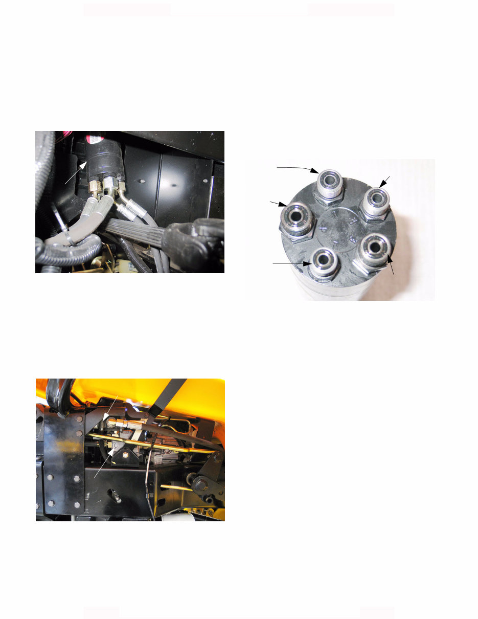
Domestic Series 5000 Hydraulics 2 1.6. The steering and lift cylinder are also powered by the a Sauer-Danfoss SNP 1/2.6 S auxiliary pump. 1.7. The steering unit, located in the dash pedestal contains it’s own back-up gerotor charge pump that will enable steering control when the engine is not running. See Figure 1.7. 1.8. The steering unit directs fluid pressure to one end of the double-acting differential steering cyl- inder while allowing it to return from the other end of the cylinder in order to provide steering action. 1.9. The lift cylinder is operated by a control valve under the right rear fender. See Figure 1.9. 1.10. The control valve directs fluid pressure to a sin- gle-acting hydraulic cylinder that lifts the three- point lift arms. 1.11. The hydraulic fluid flow is as follows: 1.12. Through the pick-up tube from the transmission sump and filter, to the auxiliary pump. 1.13. Under pressure from the auxiliary pump the fluid goes to the hydrostatic drive and to the “P” port on the steering unit. See Figure 1.13. 1.14. The steering unit distributes pressure to the steering cylinder according to the position of the steering wheel. Left turn input from the steering wheel forces fluid out the port labeled “L” and allows displaced fluid to return through the port labeled “R”. NOTE: The power steering unit is first in line, and has priority over the rest of the system. 1.15. For left turns, the fluid flows from the L port to the base end of the steering cylinder. This causes the ram to extend, turning the wheels to the left. 1.16. The steering cylinder is double-acting: As the piston is forced down the length of the cylinder by hydraulic pressure from the L port, fluid on the ram side of the piston is displaced, returning through the R port. Figure 1.7 Steering unit Figure 1.9 Auxiliary pump Lift control valve Figure 1.13 L port (pressure to turn left) R port P port (pressure from pump) T port (returns fluid to transmission) E port turn right) (pressure to (pressure lift valve) to
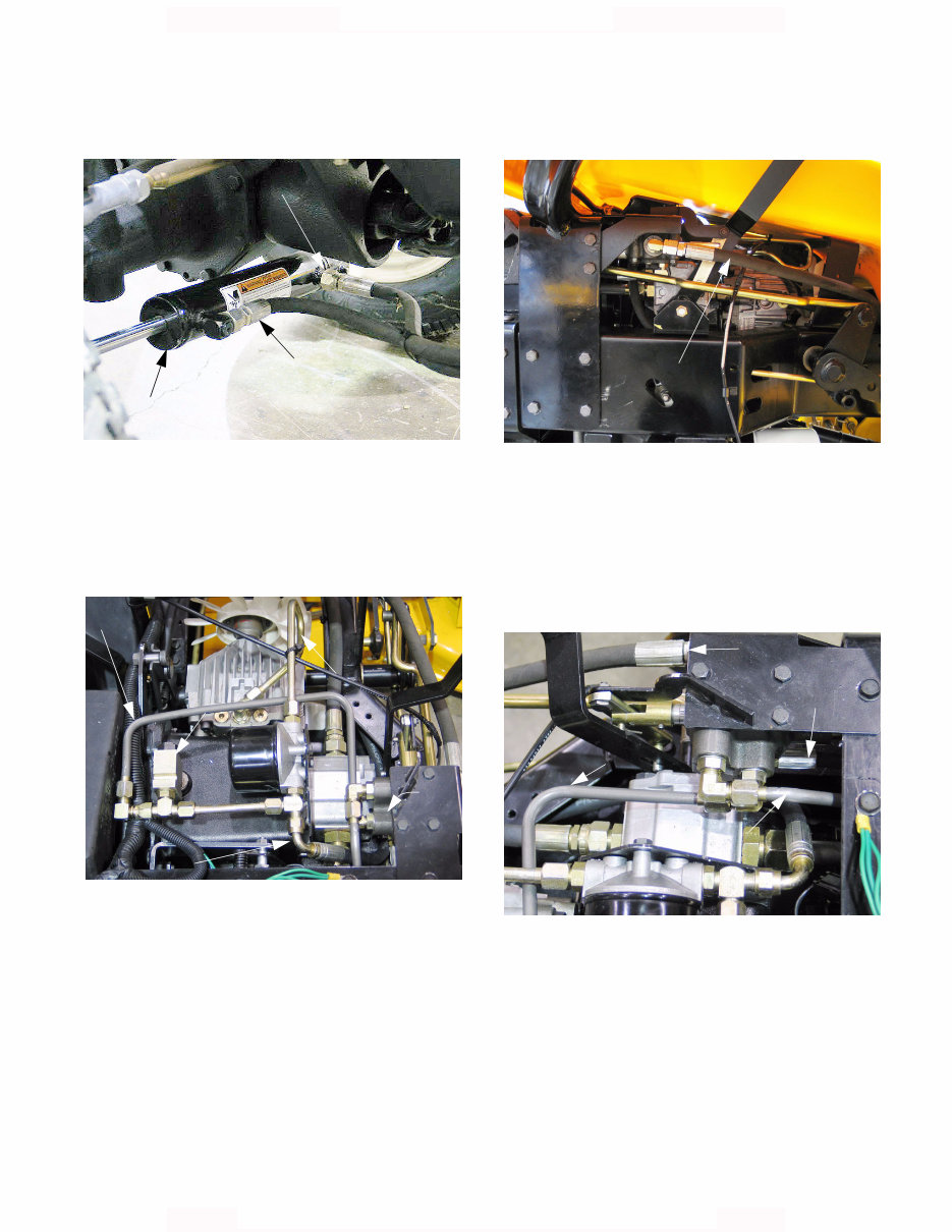
Domestic Series 5000 Hydraulics 3 1.17. The process is reversed for right turns. See Figure 1.17. 1.18. From the steering system, the fluid may follow one of two return paths: 1.19. The fluid may pass through the T port, to the return manifold. See Figure 1.19. 1.20. From the return manifold, the fluid may be directed through the hydrostatic drive filter, to provide charge pressure to the hydrostatic drive. 1.21. Pressure is maintained to the filter and hydro- static drive by a spring loaded check valve. The check valve in this application acts to maintain at least 30 PSI (2.07 Bars) of hydraulic pressure in the system. Above 30 PSI, it allows fluid to return to the reservoir (transmission housing). Figure 1.17 Steering cylinder Pressure from R port (right turn) Pressure from L port (left turn) Figure 1.19 Fluid return from T port Fluid return from lift valve 30 PSI check valve Lift valve Charge pressure (30 PSI) 1.22. From the E port, fluid will travel to the lift control valve. See Figure 1.22. 1.23. The fluid pressure that comes out of the E port goes to the outboard port of the lift control valve. 1.24. The lift control valve directs pressure to the sin- gle-acting lift cylinder through the elbow on the bottom of the valve when operator control input directs it to do so. See Figure 1.24. 1.25. Fluid not required to power the lift cylinder will be continuously directed back to the transmission through the lower inboard port (forward facing elbow) via the return manifold. Figure 1.22 Pressure from E port Figure 1.24 Pressure to lift control valve Pressure to lift cylinder Direct return (on down-stroke) Return via return manifold
Domestic Series 5000 Hydraulics 4 1.26. When the tractor operator moves the control lever forward to lower the three point hitch, the lift control valve allows fluid to escape from the lift cylinder as the cylinder retracts under the weight of any accessories supported by the hitch. 1.27. Increased fluid volume beyond normal return flow rate is generated when the lift arms are low- ered. This flow is exhausted through the top inboard port (rearward facing elbow) back into the transmission housing via a separate return tube. See Figure 1.27. 2. HYDROSTATIC DRIVE: BASIC OPERATION 2.1. The input shaft to the BDU-21L-400 turns a shaft that passes completely through the housing of the hydro., driving an engine speed input shaft in the transmission. 2.2. The input shaft drives the auxiliary hydraulic pump and the P.T.O. They are driven at rela- tively constant engine speed, rather than in rela- tion to ground speed. See Figure 2.2. 2.3. The lower part of the pump contains a fixed dis- placement axial piston hydraulic motor. The motor is driven by the output of the variable dis- placement pump. 2.4. The hydro. control arm (scissors bracket) moves a swash plate that controls the output of the pump. Figure 1.27 Direct return from lift valve Figure 2.2 PTO clutch PTO shaft Pinion gears driving auxiliary pump Traction drive pinion Figure 2.4 Scissors bracket Hydro control arm Set screw
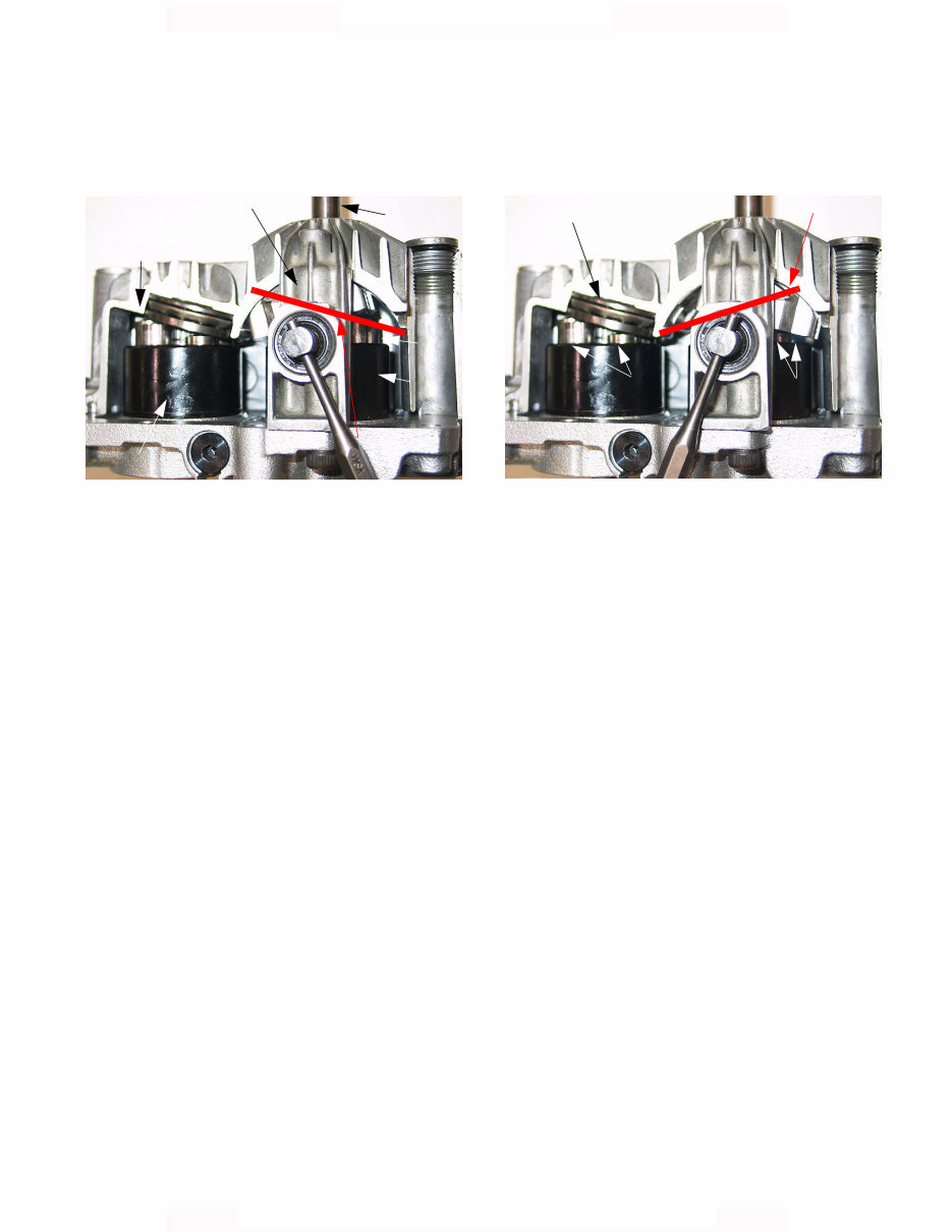
Domestic Series 5000 Hydraulics 5 2.5. : tilting the swash plate in one way causes the variable displacement pump to drive fluid through the fixed displacement pump in one direction. See Figure 2.5. NOTE: In figure 2.5, the pistons in the variable displacement pump are alternately pressed into the bores, and then released from bores of the rotating pump block by the tilt of the swash plate. • On the right side of the pump block in figure 2.5, the pistons are down. • The pistons are extended on the left side of the pump block. They are forced up by springs con- tained in the pistons. • This action causes the pistons to pump fluid in one direction. • The further the swash plate is tilted, the greater the movement of the pistons as the pump block rotates. • As the travel of the pistons is increased, the dis- placement of the pump is increased, and more fluid is pumped. • The more fluid is pumped, the faster the fixed displacement motor is driven. Figure 2.5 Input shaft Fixed displacement motor Variable displacement pump Pump block angle Swash plate Swash plate Motor block 2.6. Tilting the swash plate the other way causes the variable displacement pump to drive fluid through the fixed displacement pump in the opposite direction. See Figure 2.6. 2.7. When the swash plate is flat, the pump pistons do not move up and down, no fluid is displaced and no power is transmitted to the fixed dis- placement pump. 2.8. The auxiliary pump maintains a supply of pres- surized fluid (charge pressure) to the variable displacement pump to feed and lubricate the pump. 2.9. The charge check valves direct the flow of pres- surized fluid to the ports that feed the pistons of the variable displacement pump. • When driving forward, fluid flows into the vari- able displacement pump through one set of ports, and out through a second set. • When driving backwards, the flow is reversed. • One check valve opens and the other one closes, depending on the direction of fluid flow. • If the hydro. is in “neutral”, lubrication is provided to this spinning (but not pumping) pump and motor blocks through separate channels in the housing. 2.10. If the hydrostatic drive is not performing cor- rectly, begin diagnosing with simple things that can be seen with minimal disassembly. Figure 2.6 Swash plate angle Pistons Pistons Fixed displacement motor
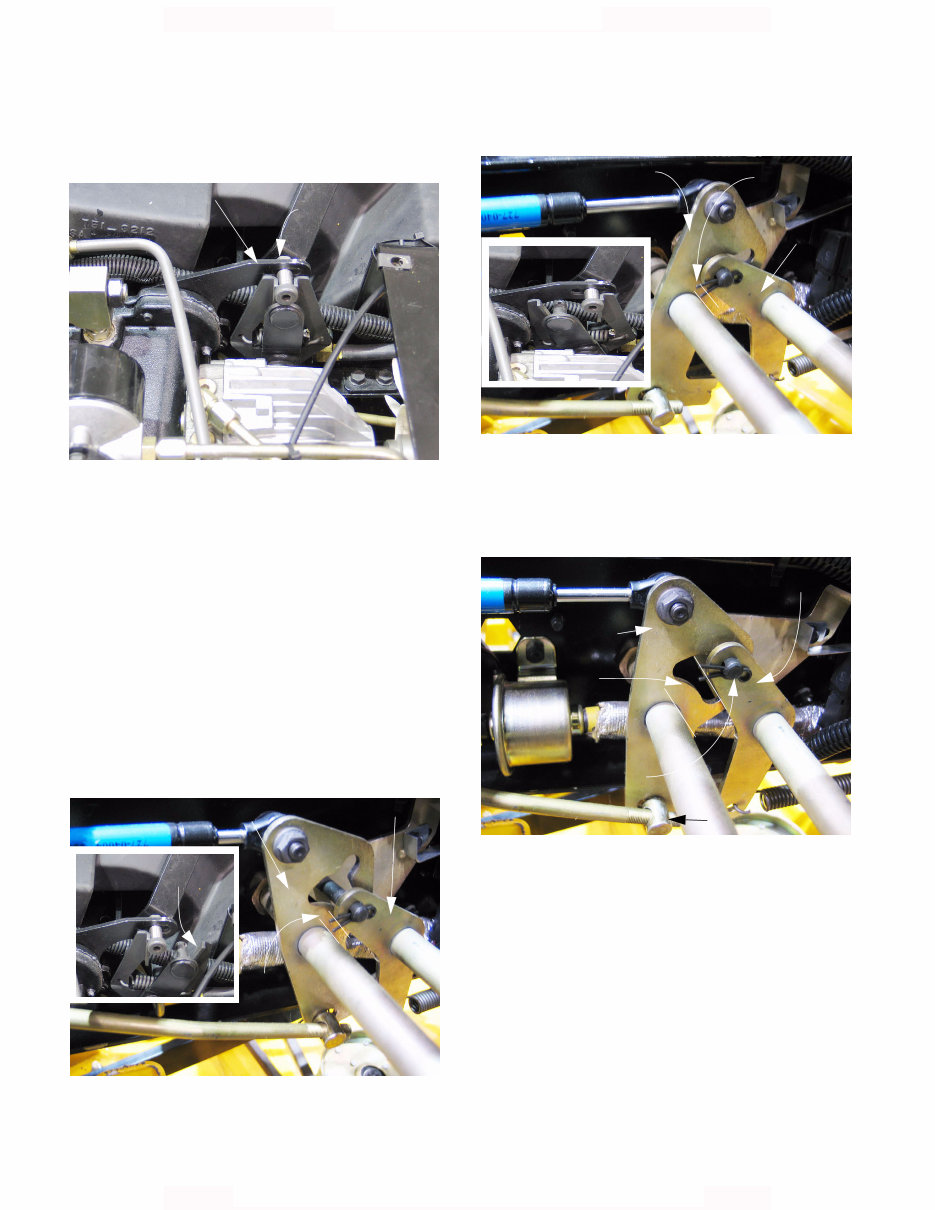
Domestic Series 5000 Hydraulics 6 3. EXTERNAL CHECKS 3.1. If the transmission creeps, check the neutral control adjustment. See Figure 3.1. NOTE: Complete neutral control adjustment pro- cedures can be found in the 2004 Cub Cadet Technical C.D. 3.2. If the tractor fails to achieve full ground speed, check the adjustment of the linkages that control the hydrostatic drive system. NOTE: Advertised maximum ground speed High range forward:8 MPH (12.9 KPH) Low range forward: 4 MPH (6.44 KPH) High range reverse:4 MPH (6.44 KPH) Low range reverse: 2 MPH (3.22 KPH) 3.3. Confirm that full travel is achieved in the forward direction. See Figure 3.3. 3.4. Confirm that full travel is achieved in the reverse direction. See Figure 3.4. 3.5. If the brake and drive pedals “fight” with each other, the drive control rod is out of adjustment. See Figure 3.5. NOTE: Isolate the hydrostatic drive unit from the linkage, and confirm the correct adjustment of the neutral return before adjusting the linkage. NOTE: After correct neutral return adjustment is established, adjust the ferrule on the drive con- trol rod so that it rests lightly against the front edge of the slot that it fits into when the parking brake is engaged. Figure 3.1 Neutral return bracket Move shoulder bolt in slot to establish neutral Figure 3.3 Hydro linkage: Forward Rod pulls hydro linkage Pedal linkage Forward Brake linkage Note: gap Figure 3.4 Hydro linkage: Reverse Pedal linkage: Reverse Brake linkage Note: gap Figure 3.5 Pedal linkage: Neutral Brake linkage: brakes applied Note: gap Pin locks linkage Drive control rod
This is a comprehensive service repair manual for the Cub Cadet Domestic 5000 Series Compact Tractor 5252 5234 5254. The manual contains easy-to-read text sections with high-quality diagrams and instructions, making it suitable for both do-it-yourself enthusiasts and experienced mechanics. It includes step-by-step instructions, detailed exploded pictures, and diagrams to assist in completing the required job correctly and efficiently.
The manual covers general information, periodic maintenance, engine, fuel system and throttle body, cooling and lubrication system, chassis, electrical system, servicing information, emission control information, wiring diagrams, and more.
This professional technical manual provides service, maintenance, and troubleshooting information for the Cub Cadet Domestic 5000 Series Compact Tractor 5252 5234 5254, encompassing all models, engines, trims, and transmission types. It is a top-quality workshop repair service manual that is complete and intact without any missing or corrupt parts or pages.
It is the same manual used in local service and repair shops, and it is guaranteed to be fully functional to save time. The manual is available in English and is printable without any restrictions. The file format is PDF, and it requires Adobe Reader. Upon payment completion, the download link will appear on the checkout page, allowing for instant access without any shipping fees.
Buyers can make payments via PayPal or Credit Card, and the download link will be available instantly after payment. This service repair manual is an invaluable resource for maintaining and repairing the Cub Cadet Domestic 5000 Series Compact Tractor 5252 5234 5254.
Recently Viewed
5,521,897Happy Clients
2,594,462eManuals
1,120,453Trusted Sellers
15Years in Business
Price:
Actual Price:
Cub-Cadet Domestic 5000 Series Compact Tractor Service Manual