

CASE 580C 580CK BACKHOE Loader Tractor Workshop Service Repair Manual
What's Included?
Fast Download Speeds
Online & Offline Access
Access PDF Contents & Bookmarks
Full Search Facility
Print one or all pages of your manual
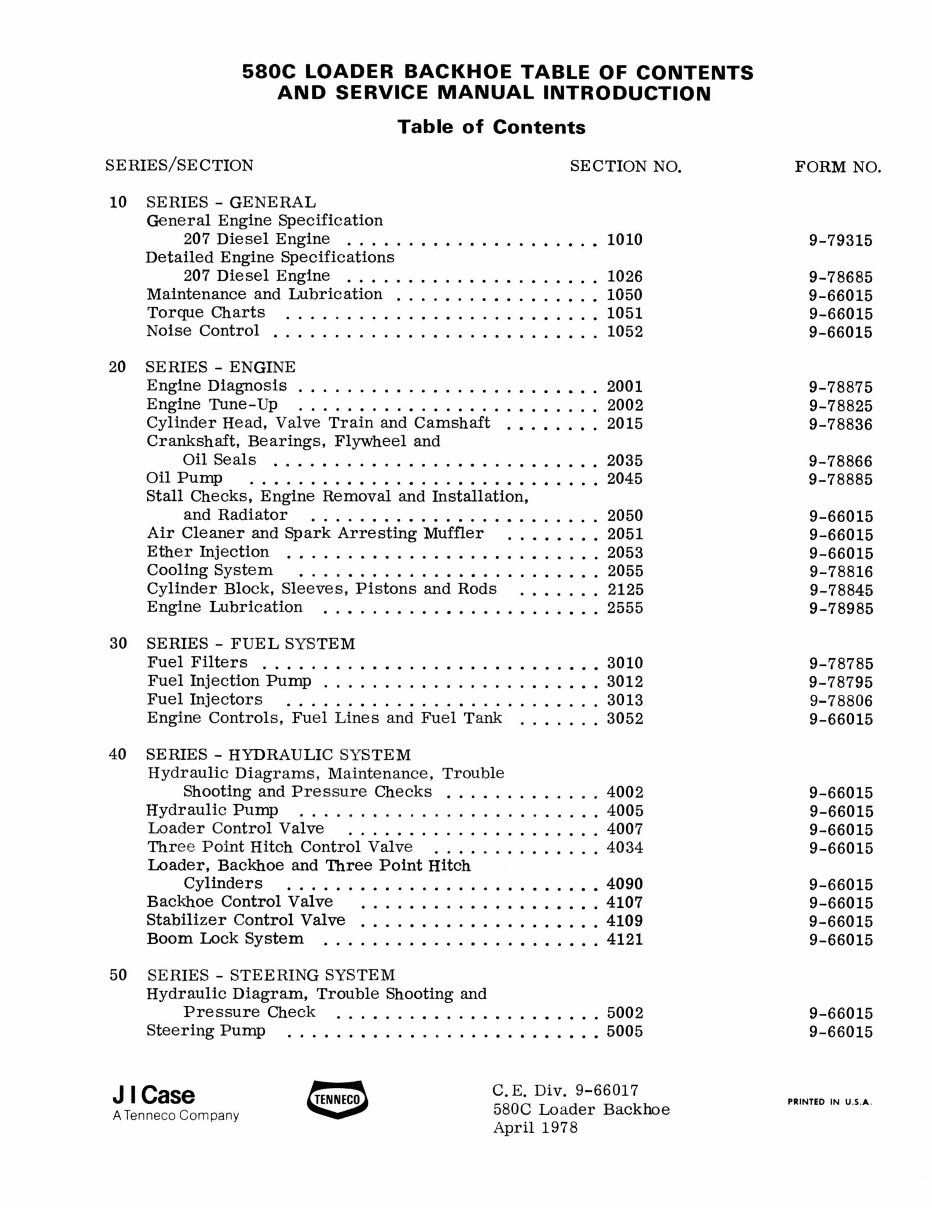
580C LOADER BACKHOE TABLE OF CONTENTS
AND SERVICE MANUAL INTRODUCTION
Table of Contents
SERIES/SE CTION
10 SERIES - GENERAL
General Engine Specification
SECTION NO.
207 Diesel Engine ...... • ........... •.• 1010
Detailed Engine Specifications
207 Diesel Engine ............. • ....... 1026
Maintenance and Lubrication ................. 1050
Torque Charts .......................... 1051
Noise Control ................... • ...... . 1052
20 SERIES - ENGINE
Engine Diagnosis . . . . . . • . . . . . . . . . . . • . • • • . . 2001
Engine Tune-Up ......................... 2002
Cylinder Head, Valve Train and. Camshaft .•.•..•. 2015
Crankshaft, Bearings, Flywheel and
Oil Seals ........ • ....... • .... •..•.. 2035
Oil PuInp ....... •••.•.•...•...•• ...... 2045
Stall Checks, Engine Removal and Installation,
and Radiator ...... • ......... •• ...... 2050
Air Cleaner and Spark Arresting Muffler ...••••. 2051
Ether Injection ....... • ...... • ..... •.. . .. 2053
Cooling System ............. •• ..... •••.. 2055
Cylinder. Block, Sleeves, Pistons and Rods ....... 2125
Engine Lubrication ..• ..... •.•• ........ •.. 2555
30 SERIES - FUEL SYSTEM
Fuel Filters ............... •...• ..... ••• 3010
Fuel Injection PuInp ..................... •. 3012
Fuel Injectors .......................... 3013
Engine Controls, Fuel Lines and Fuel Tank ....... 3052
40 SERIES - HYDRAULIC SYSTEM
Hydraulic Diagrams , Maintenance, Trouble
Shooting and Pressure Checks ............. 4002
Hydraulic PUInp ...... • .................. 4005
Loader Control Valve ..................... 4007
Three Point Hitch Control Valve ............. . 4034
Loader, Backhoe and Three Point Hitch
Cylinders ............ •• ...... ••..•• 4090
Backhoe Control Valve ............ •.•.•.•. 4107
Stabilizer Control Valve .... •..• ...... •••... 4109
Boom Lock System ..... •..•.•.•...• ...... 4121
50 SERIES - STEERING SYSTEM
Hydraulic Diagram, Trouble Shooting and
Pressure Check ................. • .... 5002
Steering Pump ................... •.•.•.• 5005
J I Case
A Tenneco Company
C. E. Div. 9-66017
580C Loader Backhoe
April 1978
FORM NO.
9-79315
9-78685
9-66015
9-66015
9-66015
9-78875
9-78825
9-78836
9-78866
9-78885
9-66015
9-66015
9-66015
9-78816
9-78845
9-78985
9-78785
9-78795
9-78806
9-66015
9-66015
9-66015
9-66015
9-66015
9-66015
9-66015
9-66015
9-66015
9-66015
9-66015
PRINTED IN U.S.A .
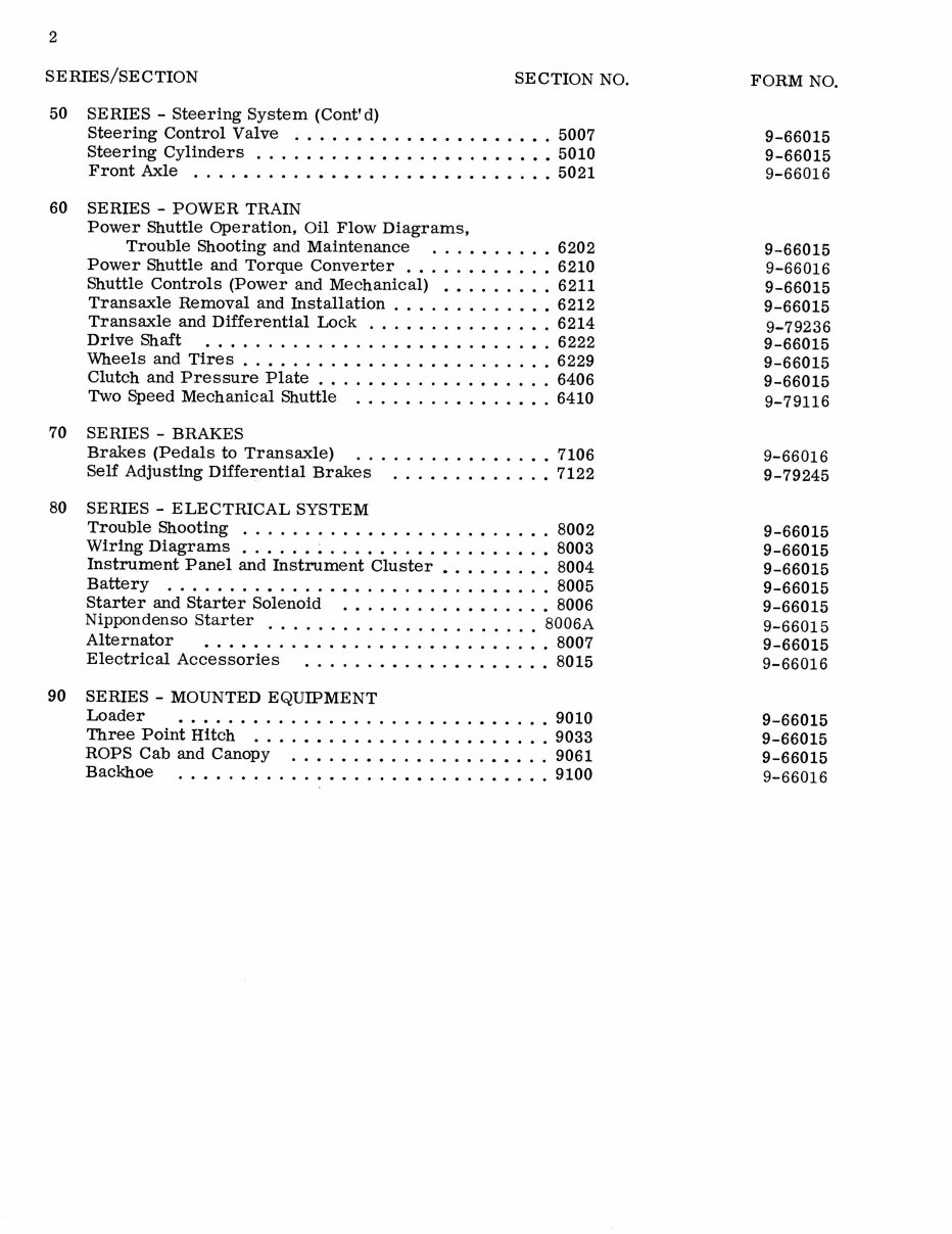
2
SERIES/SECTION SECTION NO.
50 SERIES - Steering System (ContI d)
Steering Control Valve ..... ••..•••.•.•••••. 5007
Steering Cylinders ........ •••••..•..•.•••• 5010
Front Axle ..•.• ..... •••••..••••• ....... 5021
60 SERIES - POWER TRAIN
Power Shuttle Operation, Oil Flow Diagrams,
Trouble Shooting and Maintenance ...•• ..... 6202
Power Shuttle and Torque Converter .•...•.••..• 6210
Shuttle Controls (Power and Mechanical) •••• ..... 6211
Transaxle Removal and Installation .......... •.• 6212
Transaxle and Differential Lock ...• ........ ••. 6214
Drive Shaft ..• ............. • ......... •. 6222
'Wheels and Tires ..•• ............ •• ....... 6229
Clutch and Pressure Plate ............ ••• .... 6406
Two Speed Mechanical Shuttle .... •...•.•.•... 6410
70 SERIES - BRAKES
Brakes (Pedals to Transaxle) .. ....... •.•..•. 7106
Self Adjusting Differential Brakes ...•...• .... • 7122
80 SERIES - ELECTRICAL SYSTEM
Trouble Shooting .......... • ............ •. 8002
Wiring Diagrams • .... • ~ ....... •.• ..... •.• 8003
Instrument Panel and Instrument Cluster •••..•... 8004
Battery ........ • .... •••..•.•.•...•••.. 8005
Starter and Starter Solenoid .• ....... ••• .... • 8006
Nippondenso Starter ...................... 8006A
Alternator • . • • . . . . . . . • . . . . . . . . . . . . . . . . 8007
Electrical Accessories ....... •.•..• ....... 8015
90 SERIES - MOUNTED EQUIPMENT
Loader •.•..• .............. •.•.•••..• 9010
Three Point Hitch ..•.•••••••••..•••..•.•. 9033
ROPS Cab and Canopy ..•.•.••..•...•.•••.. 9061
Backhoe ..... •...•..• .... ••• .......... 9100
FORM NO.
9-66015
9-66015
9-66016
9-66015
9-66016
9-66015
9-66015
9-79236
9-66015
9-66015
9-66015
9-79116
9-66016
9-79245
9-66015
9-66015
9-66015
9-66015
9-66015
9-66015
9-66015
9-66016
9-66015
9-66015
9-66015
9-66016
3
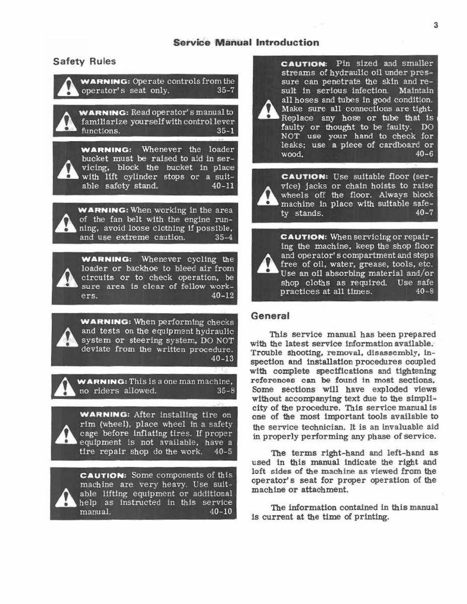
Service Manual Introduction
Safety Rules
/). WARNING: Operatt:! controls from the
.. ope r ato r's seat only. 35-;
/). WARNING: Read operator' s manual to
.. faromarize yourseJfwith controllevcr
functions. 35-1
WARNING : Whenever the loader
bucket must be rai sed to a1d in ser-
r... vicing. block the bucket In place
.. with 11ft cyl1nder stops or a suit-
able safety stand. 40-11
WARNING : When working in the area
/). of the fan belt with the engine run-
.. ning. avoid loose clothing If pOSSIble .
and use extreme C3'.1tion. 35-4
WARNING: Whenever cyCl1ng Ute
A
l oade r or backhoe to bleec air from
circuits or to check operation, be
sure area Is clcnr of fellow work-
ers. 40 -12
WARNING: When performtng ch ec~s
A and tests on the equtpm2nt hydraultc
.. system or steering systel1"., DO l'\OT
devIa te from the wr itten procedure.
40-13
~ WARNING : ThiS is a one man machine,
.. no riders allowed. 3!J - t'
WARNING: After Installlng tire on
A
riro (wheel), place wh ee l In a saft:ty
cage before inflaUng tires. If proper
equIpment Is not available, ha\'e a
tir e repair shop do the work. 40-5
CAUTION: Some components of this
machine are very heavy. ese sult-
h ab le lifting equipment or additional
.. help as Instructed in this service
manuaL 40-10
General
'Ibis service manual has been prepared
with the latest service information avaUable.
Trouble Shooting, removal, disass e mbl y. in -
spection and installation procedures coupled
with complete specific ations a!ld tightening
referonces oan be found In most sections .
Some sections will have exploded views
without accompanying text due to the simpl1-
city of the procedure. This service manual1s
one of the most Important tools available to
the servi ce technician. It is an invaluable aid
in properly performing any phase of service.
The terms right-band and le ft - hand as
used In this manual indicate the right and
left sides of the mach ine as viewed from the
operator' 6 seat for proper operation of the
machine or attachment .
The information contained in this manual
is current at the time of printing.
http://stores.ebay.com/UsefulCDs
4
Table of Contents
The preceedlng pages contain a Table of
Contents wblcb 118t the Series number and
title, and the sections contained in each series.
The individual sections, where required. will
have a Table of Contents on the second page
of that section.
Page Numbers
All page numbers consist of two sets of
digits separated by a daSh, such as 4002-9.
The digits preceeding the daSh identify the
section. The digits following the dasb repre-
sent the conaecutive page mllnber within that
section. Page numbers will be found at the
upper right or left of each page.
Text
If this manual covers more than one
machine, or different models of component
parts (planetary axles, gear boxes, control
valves, etc.) the procedures will apply to all
unless otherwise noted.
Illustrations
Where possible, Ulustrations are placed
as close as possible to the accompanying
text and should be used as part of the text.
Serial and Model Numbers
When requisitioning repair or replace-
ment parts as it may be necessary tofurn1Sh
the parts department with one or both num-
bers Serial and model numbers will be
found in the following locations.
Machine - Plate fastened to left front
cab or canopy mounting bracket. Also
stamped on top of chassis behind left-
hand hydraulic reservoir.
Engine - Right-hand side of block below
starter.
COIT4>onent parts - plate attached to part
or number stamped in part.
Torque References
Essentially two grades of fasteners
(bolts, nuts and screws) are used on Case
machinery. They a...~ grade 5 and grade 8.
Refer to Section 1051 for torque spe cific a-
tions and means of Identification.
The specifications in Section 1051 are
standard torque values and Should be used
on all fasteners during assembly and in-
stallation unless special torque values are
noted in a particular section.
Classification of Lubricants
Oils, lubricants, and grease are classi-
fied and graded accordlngto standards recom-
mended by the Society of Automotive Engi-
neers (SAE). the American Petroleum Insti-
tute (APl), and the National Lubricating
Grease Institute (NLGI).
Engine Oil
The SAE number indicates the viscosity
of engine oils, for example, SAE ao, a single
grade oU. Engine oils are also identified by
dual numbers, SAE lOWaO, a multigrade 011.
The API clauification (MS DS SD CAl
defines 011 performance in terms of engine
usage. Only olls specified in Section 1050
should be used. These oils contain sufficient
chemical additives to provide maximum en-
gine protection. Both the SAE grade and API
designation must be found on the container.
Gear Lubricant
The SAE grade mlmber also indicates the
viscosity of gear lubricantsdeflnedbyMIL-L
-2105B. An example is SAE 90, a medlumvi8-
cosity lubricant.
Grease
Semi - soUd lubricants specified for pivot
points must be that specified in Section 1050.
Section
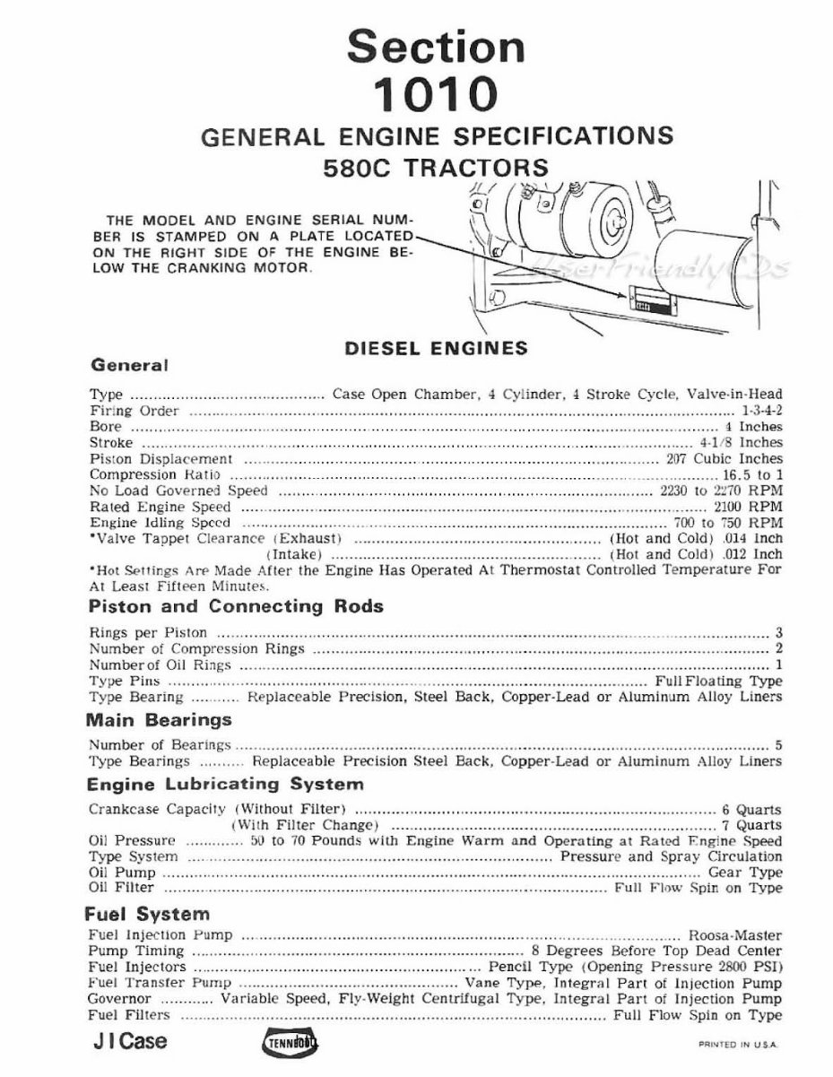
1010
GENERAL ENGINE SPECIFICATIONS
580C TRACTORS
THE MODEL AND ENGINE SERIAL NUM-
BER IS STAMPED ON A PLATE LOCATED
ON THE RIGHT sIDe OF THE ENGINE BE·
lOW THE CRANKING MOTOR .
%( (~~ \~ I'
~~ I@---" ' I'
~ ,
~
iO
DIESEL ENGINES
General
Type ........ . ....... . ....... ..... ........ ..... CasE" O pen Cham ber, ..J Cylinder, ~ S t ro k~ Cycle. Valve· in-Hea d
Firing Order ... .... ...... ..... ......... .. .................... . .. ........... .......... . .................. .... .............. . ......... 1·3· 4-2
Bo re ....... ... ", ... ... n ... ...... .. .... . . ... . .. .... . . .. .... .. . .. . .. .. .. . .... .. .. ... ...... .. . ...... . . . ... .......... ... . .. ... . . .... . 4 Inches
Stroke .......... ........... ..... .. ...... ............... .............. ..... ....... .. ...... ............ .... ......... ............. 4·1/8 Inches
Pi ston Displacement ... ... ...... ....... ...... . ............ . ............ . .... .... ......... .......... .... .. ...... 207 Cubic In c hes
Com pre ssion Harlo ........................................... ............... .. ........ ............ , .... ..... ... ... ..... 16 .5 to 1
t\o Load Governed Speed ..... .. .... .. ... ........................ .. ............................... .. .. .... 2230 to 2:170 R PM
Rated Engine Speed ....... .. .......... .. ....... .. ... .. ............ .. .. .. ............................... .. ............... . 2100 RPM
Engine Idling S pc' cd ......... ..... ......... ... .. .. .. .... .. ................. ..... ....... .. ............. ... ...... 700 to 750 RPM
·Valve TappE't Clea r ance I£ xhaust) ..................... . ........... .. .. . ......... .... ... (Hot a nd COl d) ,014 In ch
(Intake) ...... ... .......... ................. ....... . ........ . ...... ( Ho t and Cold ) . 01 2 lnch
-H ot Settir!g!> AN' Made After the En gi ne Ha s Operated At The rm ostat Controlled Te m perature For
At Least Fifteen Min ute s.
Piston and Connecting Rods
R ings per Pis ton .... ................. . .......... ,............. ..................... . ............. ... .... .... ... ...... ... ..... ........... 3
Number of Com pression Rings .. ................................. .. ............................................................... 2
Num berof Oil Rings ......... ......... .. ...................... .. ...... .. ................... .. ..... .. .... .. .. ................. .. ......... 1
Type Pill S ..... .. .................................................... .................. . ................... ....... Full Floating Type
T ype Beari ng ....... ... . Replace a ble Precision. Stee l Back. Copper ·Lead or Alumi num Alloy Liners
Main Bearings
Number of Bear ings .. ................. .. ...... .. ... .......... .................. .. .. ... . .......... ..... .... ......... .. ........... . ....... 5
Type Bea rings .... . .. ... Replaceable Pr ecisio n Steel Back . Cop per · Lead or Alum i num Alloy Li ners
Engine Lubricating System
Crankcase Capacity (Without Filter) ............ ... ... ..... ...... ..... .................................. . .......... 6 Quarts
( With Filler Cha ng(' ) .... . ........ ......... .... ... ................ . ................... ... .. . 7 Qua rts
Oi l Pressure ..... .. ... . .. 50 to 70 Pounds with Engine Warm a. nd Operati ng at R atoo F. ng in £> Speed
1'ypI? System ...... .. ..................................... .. ... .. . ... ...... .. ...... , ... ..... Pres sure and S pr ay Ci r cu lati on
Oil Pump ........... ..... . ...... ... . ......... . ...... ...... ..................... . ............ . ............................... ... Gear Type
Oil Filter ..... ...................... .... ...... .... .............. .... .. ...... .. ... . .......... . .......... ... Full F lnw Spir , on Type
Fuel System
Fuel In je-c tion Pump ...... . ............. .. ........... .............. .............. ....... ............. ... . ...... .... Roosa· Mast er
Pump Timing ..................... ..... ............. ... ................ .. ............ . 8 Degrees Before Top Dead Center
Fuel [nject ors ................ ......... ...... .. ............. ........... ...... Pen cil Type ( Opening Pressure 2800 PSI)
Fuel Tran sr er Pump ... ............... .. ....................... ..... Vane TypP , Inlegr;)1 Part of In jection Pump
Gove rn or ....... .. ... Vilfiable Speed, Fly·Wei ght Centrifuga l Ty pe . In tegral Part of I njection Pump
Fuel Fi Jters ................................................ . ........ . ........ . ..... .. ...... .. ..... Full Flow Spin on Type
J I Case ~~''''E D 'N us .. .

http://stores.ebay.com/UsefulCDs
This Page is Blank
http://stores.ebay.com/UsefulCDs
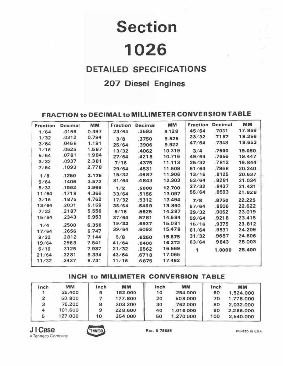
Section
1026
DETAILED SPECIFICATIONS
207 Diesel Engines
FRACTION to OECIMALto MILLIMETER CONVERSION TABLE
fraction Decimal MM Fraction Decimal MM Fraction Decimal MM
1/ 64 . 0156 0. 397 23 / 64 .3593 9.128
45 / 64 .70 31 17. 859
1/32
. 0312 0. 794
3/8 . 3750 9.525
23/32 .7187 19. 266
3/ 64
. 0468 1.191
26 / 64 . 3906 9.922
47 / 64 . 7343
18. 653
1/ 16 . 0625 , . 587
13 / 32 .4062 10.319
3/'
.7500 19.050
5/ 64 .0 781 1. 984
27 / 64 . 4218 10.716 49 / 64 . 7656 19.447
3 /32 .0937 2. 381
7/ 16 .4376 11.113 25/32 . 7812 19 . B44
7/ 64 , 1093 2. 778
29/ 64 . 4531 '1.509
61 / 64 . 7968 20.240
1/8 . 1250 3. 175
15 / 32 . 4687 11.906 13 / 16 . SUS 20 . 637
9/ 64 .1 406 3.572
31 / 64 . 4843 12.303 53/64 .8281 21 . 034
5/ 32 . 1562 3. 969
1/ '
.5000 12. 700
27 / 32 . 8437 21 . 431
11 / 64 . 1718 4. 366
33 / 64 . 5166 13.097
55/64 . 8593 21,828
3/ 16 . 1875 4. 762
17 / 32 .5312 13.494
7/8 . 8750 22 . 225
13 / 84 .20 31 5. 159
35 / 64 .5468 13.890
67 / 64 . 8906 22 . 622
7/32 . 2187 5. 556
9/ 16 . 5625 14.287
29 / 32 . 9062 23 . 019
15 / 64 . 2343 5.953
37 / 64 . 5781
14.684
59 / 64 .9 218 23 . 415
1/, . 2500 6.350
19 / 32 . 6937 16 . 081
16/16 .9375 23 . 812
17 / 54 . 2655 5. 747
39 / 64 .6093 15 . 478
61 / 64 . 9531 24 . 209
9/ 32 .2 B12 7. 144 5/ 8 .6250
15.875
31 / 32 . 9687 24 . 606
19 / 54 .296B 7.541 41 / 64 . 6406
16 .272 63 / 64 . 9843 26 . 003
5/ 16 .3 125 7.937 21 / 32 . 6562
16 .669
1 1. 0000 25.400
21 / 54 . 3281 8. 334 43 / 64 . 6718
17. 065
11 /3 2 . 3437 8. 731 11 / 16 .6875
, 7 .462
INCH to MILLIMETER CONVERSION TABLE
Inch MM Inch MM Inch MM Inch MM
,
25.400
•
, 52 . 000
10 254 .000 60 1.524 . 000
2 50. 800
7 177 . 800 20 508 .000 70 1.778.000
3 76 .200 8 203 . 200 30 762 .000 80 2, 032.000
,
101 . 600 9 228 . 600 40 , .016 .000 90 2,286.000
5
127 . 000
'0
254.000 50 1, 270 .000 100 2.540 . 000
J I Case
Rae. 9·78686
........ ED IN \I.s. ..
A Tenneco C omOa~y
1026-2
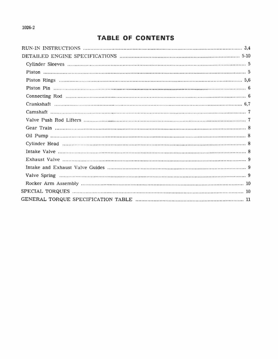
TABLE OF CONTENTS
RUN·lN INSTR UCf ION S ................ ........................... ............................................................... 3,':1
DETAILED ENGINE SPECIFICATIONS ................................................................................ 5-10
Cylinder Sleeves ....................... .. ................ ........... ..... ..................... .. ............. ........ .................. 5
Pi s lon ............. .... ... .................................................................................................................. 5
Pis ton Rings ................................. ......................................................... .......... ............ ... ..... .. 5.6
Piston Pin ..... .. ..... . ......................... .................................................................................. ...... . 6
Connecting Rod .............. . .. .. .............................................................................................. .. ..... 6
Crankshaft ...................... ........................ .................................................................. ............ 6,7
Camshaft .................................... .......................................................................... .................... 7
ValvE' Push Rod Lifters ................. ............ ............................... ......... ............................. .... .... 7
Gear Train ............................................................................................................................... 8
011 Pump ............................ ....................... ....... ................................ ........................................ 8
Cyllnder Head ....... ............................ ........ ......... ..... ............ ................. ..................... .............. 8
Intake Valve ......................... .. ................ ......... . ................. .................... ......................... .......... 8
Exhaust Valve ................. ...... ................ ................... ....................... ........................................ 9
Intake and Exhaust Valve Guides ............................................................................................ 9
Valve Spring ............................................................................................................................ 9
Rocker Arm Assembly ............................................................................................................ 10
SPECIAL TORQUES ....................... ..... ........... .......... ................ ............ .... ............... .................. 10
GENERAL TORQUE SPECIFICATION TABLE ........................................................................ 11
http://stores.ebay.com/UsefulCDs
1026-3
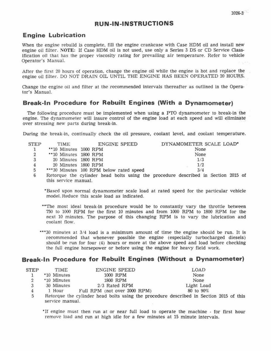
RUN-IN-INSTRUCTIONS
Engine Lubrication
Wh en tile engine rebuild is complete, fi ll the engine cra nkcase with Case HOM oil and install new
engine oil filter. NOTE: If Case HDM oil Is not used, use only a Series 3 DS or CD Service Gass-
Ification oll thaI has Ihe proper viscosity ra ting for prevailing air temperature. Refer to vehicle
Ope rator 'S Manual.
Alter the first 20 hours of operati on, change the engine oil while the engine is hot and re place the
engine oil filter. DO NOT DRAIN OIL UNTIL THE ENGINE HA S BEEN OPERATED 20 HOURS.
Change the engine oil and filter at the recomme nded intervals thereafter as outlined in the Opera·
lor's Manual.
Break-In Procedure for Rebuilt Engines (With a Dynamometer)
The following procedure must be imp lemented when usi ng a PTO dynamometer to break-in tbe
engine. The dynamometer will insure control of the engine load a l eac h speed and will e liminate
over stressing new parts during break·in.
During the break·in, continually check the 011 pressure, c oo lant level, and coolant temperature.
STEP
I
TIME ENGINE S PEED
'·10 Minutes 100.1 RPM
DYNAMOMETER SCALE LOAD-
None
2
3
4
5
6
"10 Minutes 1800 RPM
20 Minutes 1800 RPM
20 Minutes 1800 RPM
.0° 30 Minutes 100 RPM below rated speed
Ret orque the cylinder head bolts using the
this service manual.
No ne
1 /3
IJ2
3/.
procedure described In Section 2015 of
°Based upon normal dy namometer sca le load at r ated speed for the particular vehicle
model. Reduce this scale load as indicated.
"The most ideal break·in procedure would be to constantly var y the throttle between
750 to 1000 RPM for the first 10 minutes and from 1000 RPM to 1800 RPM for the
next 10 minutes. Tile purpose of this chan ging RPM is to vary the lubrication and
coolant flow.
'0' 30 minutes at 3/4 load is a minimum amount of time the engine should be run. It is
recommended that whenever possible the engine (especially tur bocharged d iesels)
should be run for four (4) hours or more at the above speed and load before chec king
the full eng ine horsepower or before using the engine for heavy field work.
Break-In Procedure for Rebuilt Engines (Without a Dynamometer)
STEP
1
2
3
•
5
TIME ENGINE SPEED
°10 Minutes 1000 RPM
' 10 Minutes 1800 RPM
30 Minutes 213 Rated RPM
1 Hour Fu ll RPM i not over 2000 RPM)
Retorque the cyUnder head bolts using the procedure
ser vice manual.
LOAD
None
None
Light Load
80 to 9O' li •
described in Section 2015 of thts
'If engine must then run at or n ea r full load to operate the mach ine - for first hour
remo ve load and run at high idle for a few minutes at 15 minute intervals.
You're Reading a Preview
What's Included?
Fast Download Speeds
Online & Offline Access
Access PDF Contents & Bookmarks
Full Search Facility
Print one or all pages of your manual
$31.99
Viewed 74 Times Today


Secure transaction
What's Included?
Fast Download Speeds
Online & Offline Access
Access PDF Contents & Bookmarks
Full Search Facility
Print one or all pages of your manual
$31.99
This manual is suitable for both first-time owners and amateur enthusiasts, as well as professional technicians. It is designed in an easy-to-read format and provides comprehensive information necessary for accurate procedure execution. It is recommended to keep this shop manual accessible and refer to it regularly. Adhering to routine and preventive maintenance outlined in the manual will contribute to time and cost savings by averting premature failure and unnecessary repairs.
- General
- Engine
- Fuel system
- Hydraulic system
- Steering system
- Power train
- Brakes
- Electrical system
File Format: PDF
Compatible with all versions of Windows & Mac
Language: English
Requirements: Adobe Reader


