CASE 5140 Tractor Workshop Service Manual for Repair
What's Included?
Lifetime Access
Fast Download Speeds
Online & Offline Access
Access PDF Contents & Bookmarks
Full Search Facility
Print one or all pages of your manual
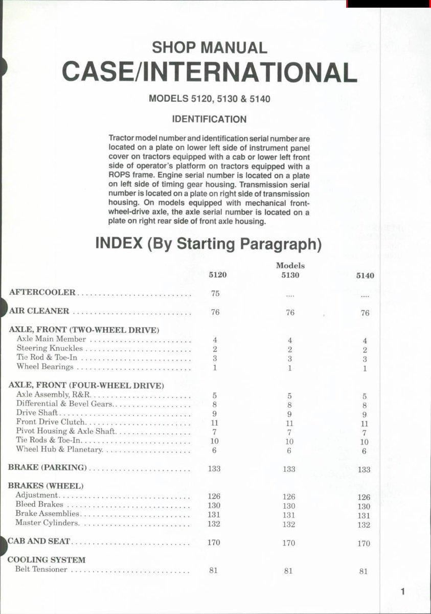
SHOP MANUAL CASE/INTERNATIONAL MODELS 5120, 5130 & 5140 IDENTIFICATION Tractor model number and identification seriai number are located on a plate on lower ieft side of instrument panel cover on tractors equipped with a cab or lower ieft front side of operator's platform on tractors equipped with a ROPS frame. Engine seriai number is located on a plate on left side of timing gear housing. Transmission seriai number is located on a plate on right side of transmission housing. On models equipped with mechanical front- wheel-drive axle, the axie seriai number is located on a plate on right rear side of front axle housing. INDEX (By Starting Paragraph) 5120 AFl ERCOOLER 75 AIR CLEANER 76 AXLE, FRONT (TWO-WHEEL DRIVE) A>:le Main Member 4 Steering Knuckles 2 Tie Rod & Toe-In 3 Wheel Bearings 1 AXLE, FRONT (FOUR WHEEL DRIVE) Ai:le Assembly, R&R 5 Differential & Bevel Gears 8 Drive Shaft 9 Front Drive Clutch 11 Pivot Housing & Axle Shaft 7 Tie Rods & Toe-in 10 Wlieel Hub & Planetary. 6 BRAKE (PARKING) 133 BRAKES (WHEEL) Adjustment 126 Bleed Brakes 130 Brake Assemblies 131 Master Cyhnders 132 k c A B AND SEAT 170 I COOLING SYSTEM Belt Tensioner 81 Models 5130 76 5140 76 4 2 3 1 5 8 9 11 7 10 6 133 126 130 131 132 4 2 3 1 5 8 9 11 7 10 6 133 126 130 131 132 170 81 170 81
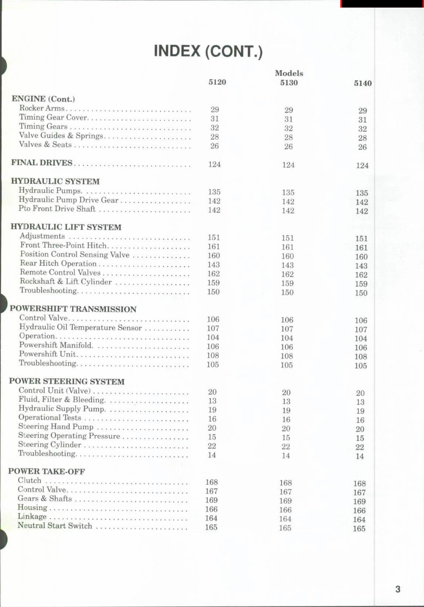
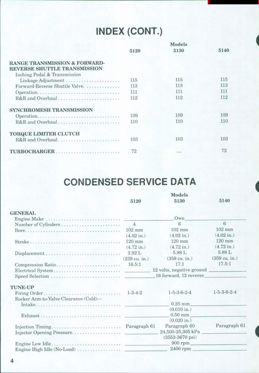
INDEX (CONT.) 5120 Models 5130 5140 RANGE TRANSMISSION & FORWARD- REVERSE SHUTTLE TRANSMISSION Inching Pedal & Transmission Linkage Adjustment 115 Forward-Reverse Shuttle Valve 113 Operation Ill R&R and Overhaul 112 SYNCHROMESH TRANSMISSION Operation 109 R&R and Overhaul 110 TORQUE LIMITER CLUTCH R&R and Overhaul 103 TURBOCHARGER 72 115 113 111 112 109 110 103 115 113 111 112 109 110 103 72 CONDENSED SERVICE DATA 5120 Models 5130 5140 GENERAL Engine Make Own Number of Cylinders 4 6 Bore 102 mm 102 mm (4.02 in.) (4.02 in.) Stroke 120 mm 120 mm (4.72 in.) (4.72 in.) Displacement 3.92 L 5.88 L (239 cu. in.) (359 cu. in.) Compression Ratio 16.5:1 17:1 Electrical System . . . 12 volts, negative ground Speed Selection 16 forward, 12 reverse_ TUNE-UP Firing Order 1-3-4-2 1-5-3-6-2-4 Rocker Arm-to-Valve Clearance (Cold)— Intake 0.25 mm (0.010 in.) Exhaust 0.50 mm (0.020 in.) Injection Timing Paragraph 61 Paragraph 60 Injector Opening Pressure 24,500-25,305 kPa (3553-3670 psi) Engine Low Idle 900 rpm Engine High Idle (No-Load) 2400 rpm 6 102 mm (4.02 in.) 120 mm (4.72 in.) 5.88 L (359 cu. in.) 17.5:1 1-5-3-6-2-4 Paragraph 61
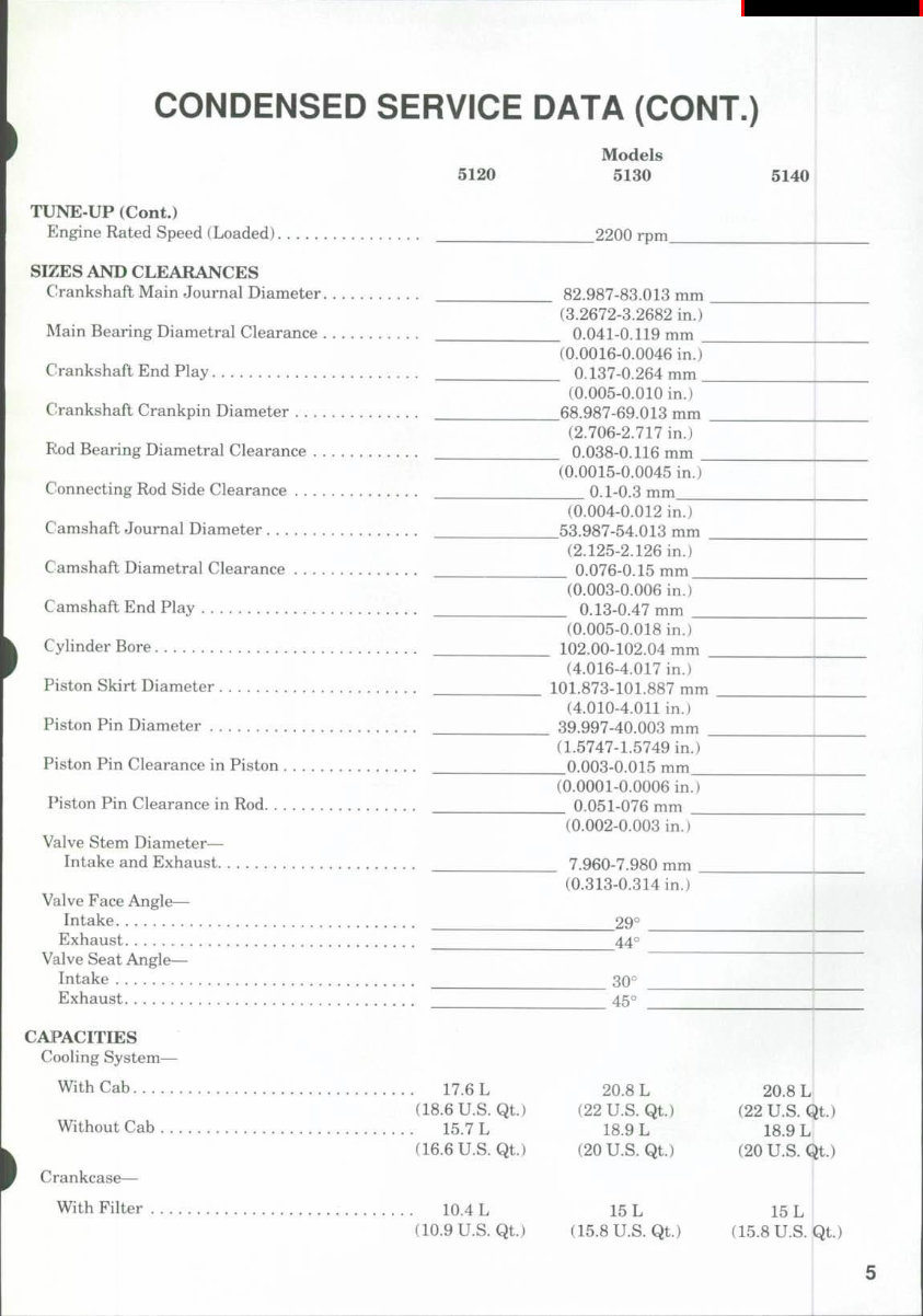
CONDENSED SERVICE DATA (CONT.) TUNE-UP (Cont.) Engine Rated Speed (Loaded) SIZES AND CLEARANCES Crankshaft Main Journal Diameter Main Bearing Diametral Clearance C!rankshaft End Play Crankshaft Crankpin Diameter Rod Bearing Diametral Clearance Connecting Rod Side Clearance Ciamshaft Journal Diameter Camshaft Diametral Clearance Camshaft End Play Cylinder Bore Piston Skirt Diameter Piston Pin Diameter Piston Pin Clearance in Piston Piston Pin Clearance in Rod Valve Stem Diameter— Intake and Exhaust Valve Face Angle— Intake Exhaust Valve Seat Angle— Intake Exhaust CAPACITIES Cooling System— With Cab Without Cab Crankcase— With Filter Models 5120 5130 5140 2200 rpm 82.987-83.013 mm (3.2672-3.2682 in.) 0.041-0.119 mm (0.0016-0.0046 in.) 0.137-0.264 mm (0.005-0.010 in.) 68.987-69.013 mm (2.706-2.717 in.) 0.038-0.116 mm (0.0015-0.0045 in.) 0-1-0.3 mm (0.004-0.012 in.) 53.987-54.013 mm (2.125-2.126 in.) 0.076-0.15 mm (0.003-0.006 in.) 0.13-0.47 mm (0.005-0.018 in.) 102.00-102.04 mm (4.016-4.017 in.) . . 101.873-101.887 mm (4.010-4.011 in.) 39.997-40.003 mm (1.5747-1.5749 in.) 0.003-0.015 mm (0.0001-0.0006 in.) 0.051-076 mm (0.002-0.003 in.) 7.960-7.980 mm (0.313-0.314 in.) 29° 44° 30° 45° 17.6 L 20.8 L 20.8 L (18.6 U.S. Qt.) (22 U.S. Qt.) (22 U.S. Q 15.7 L 18.9 L 18.9 L (16.6 U.S. Qt.) (20 U.S. Qt.) (20 U.S. Q 10.4 L 15 L 15 L (10.9 U.S. Qt.) (15.8 U.S. Qt.) (15.8 U.S. It) it.) Qt.)
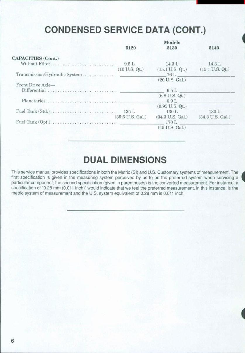
CONDENSED SERVICE DATA (CONT.) Models 5120 5130 5140 CAPACITIES (Cont.) Without Filter 9.5 L 14.3 L 14.3 L (10 U.S. Qt.) (15.1 U.S. Qt.) (15.1 U.S. Qt.) Transmission/Hydraulic System 76 L (20 U.S. Gal.) Front Drive Axle— Differential 6.5 L (6.8 U.S. Qt.) Planetaries 0.9 L (0.95 U.S. Qt.) Fuel Tank (Std.) 135 L 130 L 130 L (35.6 U.S. Gal.) (34.3 U.S. Gal.) (34.3 U.S. Gal.) Fuel Tank (Opt.) 170 L (45 U.S. Gal) DUAL DIMENSIONS This service manual provides specifications in both the Metric (SI) and U.S. Customary systems of measurement. The first specification is given in the measuring systenn perceived tDy us to be the preferred system when servicing a particular component; the second specification (given in parentheses) is the converted measurement. For instanc e, a specification of "0.28 mm (0.011 inch)" would indicate that we feel the preferred measurement, in this instance, is the metric system of measurement and the U.S. system equivalent of 0.28 mm is 0.011 inch.
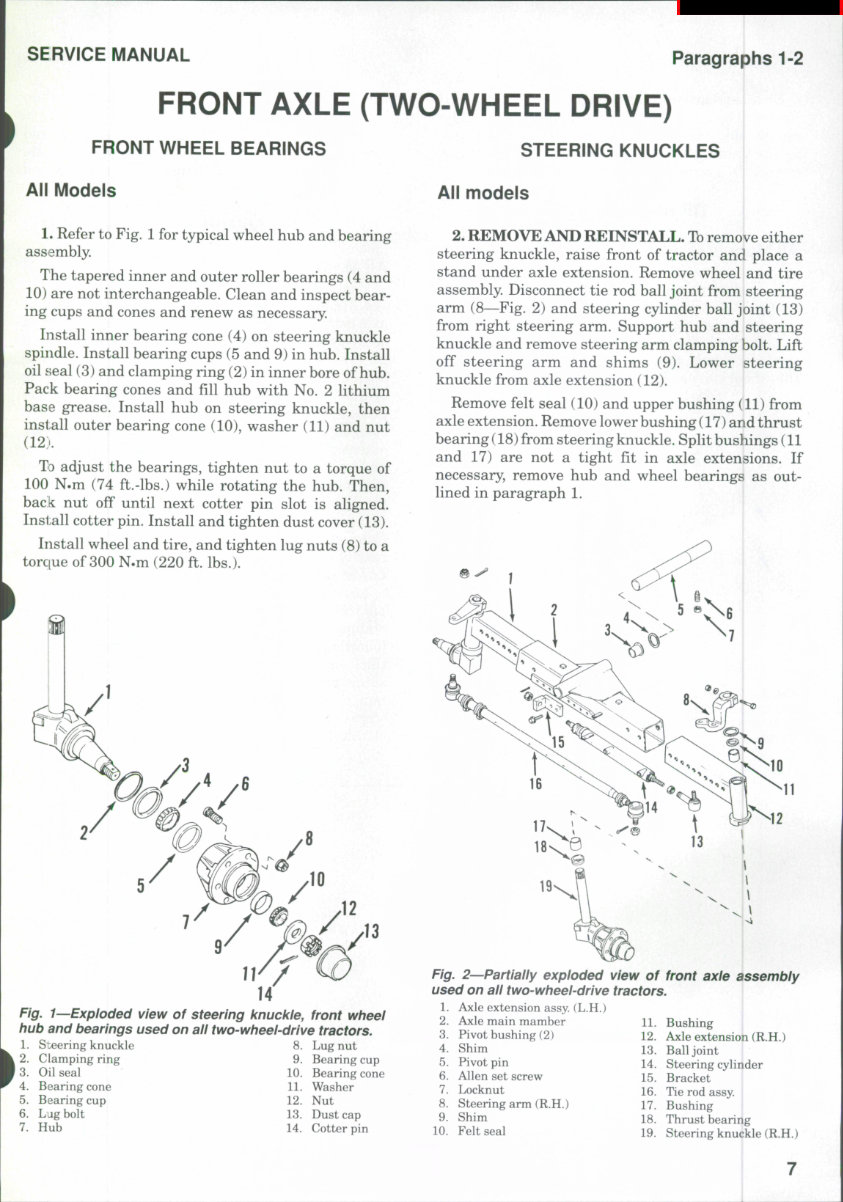
SERVICE MANUAL Paragraphs 1-2 FRONT AXLE (TWO-WHEEL DRIVE) FRONT WHEEL BEARINGS STEERING KNUCKLES All Models All models 1. Refer to Fig. 1 for typical wheel hub and bearing assembly. The tapered inner and outer roller bearings (4 and 10) are not interchangeable. Clean and inspect bear- ing cups and cones and renev^ as necessary. Install inner bearing cone (4) on steering knuckle spindle. Install bearing cups (5 and 9) in hub. Install oil seal (3) and clamping ring (2) in inner bore of hub. Pack bearing cones and fill hub with No. 2 lithium base grease. Install hub on steering knuckle, then install outer bearing cone (10), washer (11) and nut (12;'. TD adjust the bearings, tighten nut to a torque of 100 N.m (74 ft.-lbs.) while rotating the hub. Then, back nut off until next cotter pin slot is aligned. Install cotter pin. Install and tighten dust cover (13). Install wheel and tire, and tighten lug nuts (8) to a torque of 300 N.m (220 ft. lbs.). Fig. 1—Exploded view of steering knuckle, front wheel hub and bearings used on all two-wheel-drive tractors. S :eering knuckle Clamping ring Oil seal Bearing cone Bearing cup Lug bolt Hub 9. 10. 11. 12. 13. 14. Lug nut Bearing cup Bearing cone Washer Nut Dust cap Cotter pin 2. REMOVE AND REINSTALL. To remove either steering knuckle, raise front of tractor and place a stand under axle extension. Remove wheel and tire assembly. Disconnect tie rod ball joint from steering arm (8—Fig. 2) and steering cylinder ball joint (13) from right steering arm. Support hub and steering knuckle and remove steering arm clamping bolt. Lift off steering arm and shims (9). Lower steering knuckle from axle extension (12). Remove felt seal (10) and upper bushing (11) from axle extension. Remove lower bushing (17) and thrust bearing (18) from steering knuckle. Split bushings (11 and 17) are not a tight fit in axle extensions. If necessary, remove hub and wheel bearings as out- lined in paragraph 1. Fig. 2—Partially exploded view of used on all two-wheel-drive tractors 1. Axle extension assy. (L.H.) 2. Axle main mamber 11. 3. Pivot bushing (2) 12. 4. Shim 13. 5. Pivot pin 14, 6. Allen set screw 15. 7. Locknut 16. 8. Steering arm (R.H.) 17. 9. Shim 18. 10. Felt seal 19. front axle assembly Bushing Axle extension (R.H.) Ball joint Steering cylinder Bracket Tie rod assy. Bushing Thrust bearing Steering knuckle (R.H.)
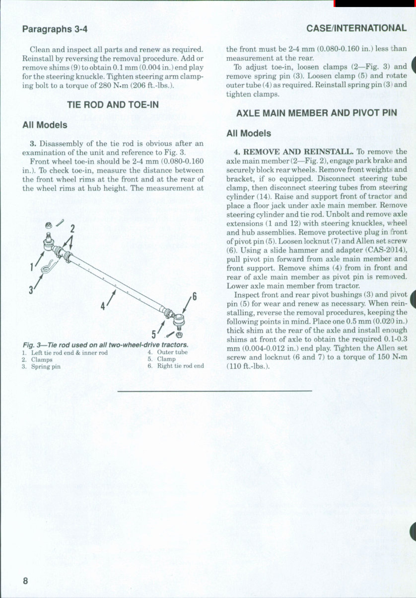
Paragraphs 3-4 CASE/INTERNATIONAL Clean and inspect all parts and renew as required. Reinstall by reversing the removal procedure. Add or remove shims (9) to obtain 0.1 mm (0.004 in.) end play for the steering knuckle. Tighten steering arm clamp- ing bolt to a torque of 280 N.m (206 ft.-lbs.). TIE ROD AND TOE-IN All Models 3. Disassembly of the tie rod is obvious after an examination of the unit and reference to Fig. 3. Front wheel toe-in should be 2-4 mm (0.080-0.160 in.). To check toe-in, measure the distance between the front wheel rims at the front and at the rear of the wheel rims at hub height. The measurement at Fig. 3—Tie rod used on all two-wheel-drive tractors. 1. Left tie rod end & inner rod 4. Outer tube 2. Clamps 5. Clamp 3. Spring pin 6. Right tie rod end the front must be 2-4 mm (0.080-0.160 in.) less ihan measurement at the rear. To adjust toe-in, loosen clamps (2—Fig. 3) and remove spring pin (3). Loosen clamp (5) and r(»tate outer tube (4) as required. Reinstall spring pin (3 • and tighten clamps. AXLE MAIN MEMBER AND PIVOT PIN All Models 4. REMOVE AND REINSTALL. To remove the axle main member (2—Fig. 2), engage park brake and securely block rear wheels. Remove front weights and bracket, if so equipped. Disconnect steering tube clamp, then disconnect steering tubes from steering cylinder (14). Raise and support front of tractor and place a floor jack under axle main member. Remove steering cylinder and tie rod. Unbolt and remove axle extensions (1 and 12) with steering knuckles, wheel and hub assemblies. Remove protective plug in *Tont of pivot pin (5). Loosen locknut (7) and Allen set screw (6). Using a slide hammer and adapter (CAS-2014), pull pivot pin forward from axle main member and front support. Remove shims (4) from in front and rear of axle main member as pivot pin is rem< »ved. Lower axle main member from tractor. Inspect front and rear pivot bushings (3) and pivot pin (5) for wear and renew as necessary. When rein- stalling, reverse the removal procedures, keeping the following points in mind. Place one 0.5 mm (0.020 in.) thick shim at the rear of the axle and install enough shims at front of axle to obtain the required 0. L-0.3 mm (0.004-0.012 in.) end play Tighten the Allen set screw and locknut (6 and 7) to a torque of 150 N.m (110 ft.-lbs.). 8
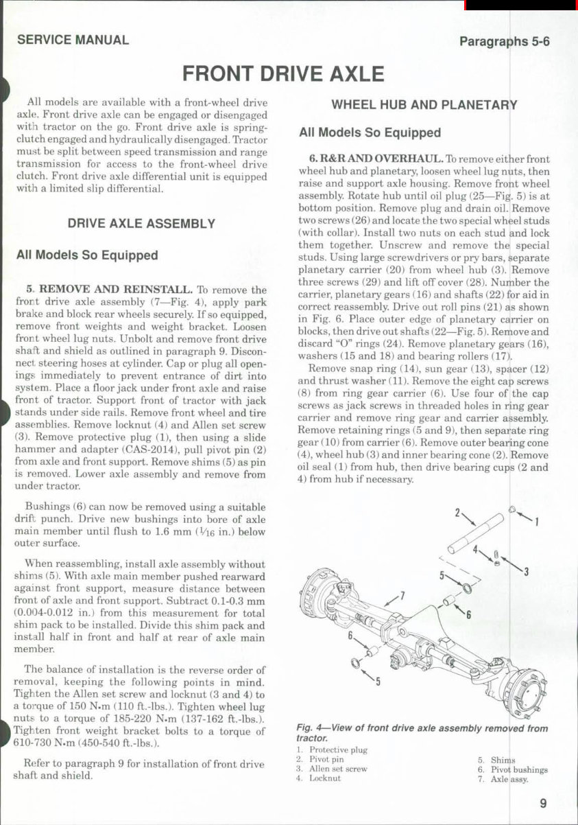
SERVICE MANUAL Paragraphs 5-6 FRONT DRIVE AXLE All models are available with a front-wheel drive axle. Front drive axle can be engaged or disengaged with tractor on the go. Front drive axle is spring- clutch engaged and hydraulically disengaged. TVactor must be split between speed transmission and range transmission for access to the front-wheel drive clutch. Front drive axle differential unit is equipped witli a limited slip differential. DRIVE AXLE ASSEMBLY All Models So Equipped 5 REMOVE AND REINSTALL. To remove the frort drive axle assembly (7—Fig. 4), apply park bra]i:e and block rear wheels securely. If so equipped, remove front weights and weight bracket. Loosen front wheel lug nuts. Unbolt and remove front drive shaft and shield as outlined in paragraph 9. Discon- nect steering hoses at cylinder. Cap or plug all open- ings immediately to prevent entrance of dirt into system. Place a fioor jack under front axle and raise front of tractor. Support front of tractor with jack I stands under side rails. Remove front wheel and tire assemblies. Remove locknut (4) and Allen set screw (3). Remove protective plug (1), then using a slide hammer and adapter (CAS-2014), pull pivot pin (2) from axle and front support. Remove shims (5) as pin is removed. Lower axle assembly and remove from under tractor. Bushings (6) can now be removed using a suitable drift punch. Drive new bushings into bore of axle main member until fiush to 1.6 mm (Vi6 in.) below outeir surface. When reassembling, install axle assembly without shims (5). With axle main member pushed rearward against front support, measure distance between front of axle and front support. Subtract 0.1-0.3 mm (0.004-0.012 in.) from this measurement for total shim pack to be installed. Divide this shim pack and install half in front and half at rear of axle main member. Tlie balance of installation is the reverse order of removal, keeping the following points in mind. Tighten the Allen set screw and locknut (3 and 4) to a torque of 150 N.m (110 ft.-lbs.). Tighten wheel lug nuts to a torque of 185-220 N.m (137-162 ft.-lbs.). I Tighten front weight bracket bolts to a torque of 610-730 N.m (450-540 ft.-lbs.). Refer to paragraph 9 for installation of front drive shaft and shield. WHEEL HUB AND PLANETARY All Models So Equipped 6. R&R AND OVERHAUL. To remove either front wheel hub and planetary, loosen wheel lug nuts, then raise and support axle housing. Remove front wheel assembly. Rotate hub until oil plug (25—Fig. 5) is at bottom position. Remove plug and drain oil. Remove two screws (26) and locate the two special wheel studs (with collar). Install two nuts on each stud and lock them together. Unscrew and remove the special studs. Using large screwdrivers or pry bars, separate planetary carrier (20) from wheel hub (3). Remove three screws (29) and lift off cover (28). Number the carrier, planetary gears (16) and shafts (22) for aid in correct reassembly. Drive out roll pins (21) as shown in Fig. 6. Place outer edge of planetary carrier on blocks, then drive out shafts (22—Fig. 5). Remove and discard "O" rings (24). Remove planetary gears (16), washers (15 and 18) and bearing rollers (17). Remove snap ring (14), sun gear (13), spacer (12) and thrust washer (11). Remove the eight cap screws (8) from ring gear carrier (6). Use four of the cap screws as jack screws in threaded holes in ring gear carrier and remove ring gear and carrier assembly. Remove retaining rings (5 and 9), then separ'ate ring gear (10) from carrier (6). Remove outer bearing cone (4), wheel hub (3) and inner bearing cone (2). Remove oil seal (1) from hub, then drive bearing cups (2 and 4) from hub if necessary. I Fig. 4—View of front drive axle assembly removed from tractor. 1. Protective plug 2. Pivot pin 5. Shims 3. Allen set screw 6. Pivot bushings 4. Locknut 7. Axle assy. I 9
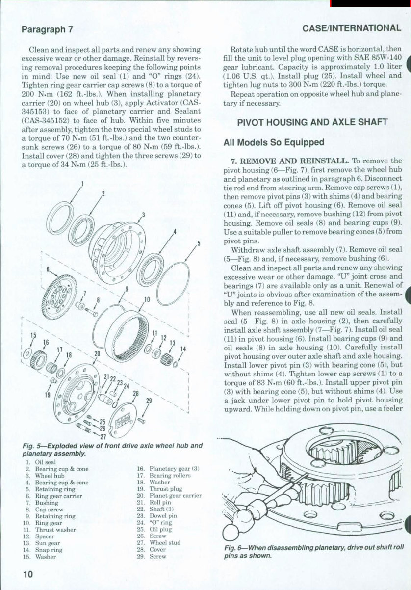
Paragraph 7 CASE/INTERNATIONAL Clean and inspect all parts and renew any showing excessive wear or other damage. Reinstall by revers- ing removal procedures keeping the following points in mind: Use new oil seal (1) and "0" rings (24). Tighten ring gear carrier cap screws (8) to a torque of 200 N.m (162 ft.-lbs.). When installing planetary carrier (20) on wheel hub (3), apply Activator (CAS- 345153) to face of planetary carrier and Sealant (CAS-345152) to face of hub. Within five minutes after assembly, tighten the two special wheel studs to a torque of 70 N.m (51 ft.-lbs.) and the two counter- sunk screws (26) to a torque of 80 N.m (59 ft.-lbs.). Install cover (28) and tighten the three screws (29) to a torque of 34 N.m (25 ft.-lbs.). Fig. 5—Exploded view of front drive axle wheel hub and planetary assembly. 1. Oil seal 2. Bearing cup & cone 3. Wheel hub 4. Bearing cup & cone 5. Retaining ring 6. Ring gear carrier 7. Bushing 8. Cap screw 9. Retaining ring 10. Ring gear 11. Thrust washer 12. Spacer 13. Sun gear 14. Snap ring 15. Washer 16. Planetary gear (3) 17. Bearing rollers 18. Washer 19. Thrust plug 20. Planet gear carrier 21. Roll pin 22. Shaft (3) 23. Dowel pin 24. "O"ring 25. Oil plug 26. Screw 27. Wheel stud 28. Cover 29. Screw Rotate hub until the word CASE is horizontal, then fill the unit to level plug opening with SAE 85W-140 gear lubricant. Capacity is approximately 1.0 liter (1.06 U.S. qt.). Install plug (25). Install wheel and tighten lug nuts to 300 N.m (220 ft.-lbs.) torque Repeat operation on opposite wheel hub and plane- tary if necessary. PIVOT HOUSING AND AXLE SHAFT All Models So Equipped 7. REMOVE AND REINSTALL. To removt the pivot housing (6—Fig. 7), first remove the wheel hub and planetary as outlined in paragraph 6. Disconnect tie rod end from steering arm. Remove cap screw s (1), then remove pivot pins (3) with shims (4) and bearing cones (5). Lift off pivot housing (6). Remove oil seal (11) and, if necessary, remove bushing (12) from pivot housing. Remove oil seals (8) and bearing cups (9). Use a suitable puller to remove bearing cones (5) from pivot pins. Withdraw axle shaft assembly (7). Remove oil seal (5—Fig. 8) and, if necessary, remove bushing (6 . Clean and inspect all parts and renew any showing excessive wear or other damage. "U" joint cross and bearings (7) are available only as a unit. Renev al of "U" joints is obvious after examination of the assem- bly and reference to Fig. 8. When reassembling, use all new oil seals. Install seal (5—Fig. 8) in axle housing (2), then care fully install axle shaft assembly (7—Fig. 7). Install oi! seal (11) in pivot housing (6). Install bearing cups (9' and oil seals (8) in axle housing (10). Carefully install pivot housing over outer axle shaft and axle housing. Install lower pivot pin (3) with bearing cone (5 , but without shims (4). Tighten lower cap screws (1 to a torque of 83 N.m (60 ft.-lbs.). Install upper pivot pin (3) with bearing cone (5), but without shims (4) Use a jack under lower pivot pin to hold pivot housing upward. While holding down on pivot pin, use a feeler i Fig^ e^When disassembling planetary, drive out shaft roll pins as shown. 10
The CASE 5140 Tractor Workshop Service Manual for Repair provides comprehensive data, characteristics, instructions, and methodology for performing repair interventions on the vehicle and its components. It includes special notes, important points, service data, precautions, and detailed illustrations, exploded diagrams, drawings, and photos to guide you through every service repair procedure. This manual is intended as a handy, easy-to-read reference book for both professional mechanics and DIY enthusiasts.
The manual is available in .PDF format and can be viewed on any computer, as well as zoomed and printed. It contains detailed explanations of all installation, removal, disassembly, assembly, repair, and check procedures laid out in sequential order. The service and repair instructions included meet all the information needs to repair or make adjustments to the CASE 5140 Tractor. It also provides general descriptions for accomplishing service and repair work with tested, effective techniques.
Information in this manual is divided into groups containing general information, diagnosis, testing, adjustments, removal, installation, disassembly, and assembly procedures for the systems and components. The manual also outlines procedures for servicing and repairing vehicles using safe, effective methods, and contains valuable reference data for adjustment values. It is designed primarily for use by trained technicians in a properly equipped workshop, but contains enough detail and basic information to make it useful to the owner who desires to perform basic maintenance and repair work.
To maximize the life of your CASE 5140 Tractor, it is essential to accurately follow the maintenance requirements, investigate unusual noises and changes in riding characteristics, use genuine parts, follow procedures carefully, keep complete records of all maintenance and repairs, and use approved lubricants as specified in the manual. The manual also emphasizes the importance of observing all accident prevention guidelines and safety measures when performing maintenance and repair work.
Overall, the CASE 5140 Tractor Workshop Service Manual for Repair is a high-quality, complete, and intact resource that provides technical information regarding the design, function, disassembly, adjusting work, and troubleshooting on the components and model of the CASE 5140 Tractor.
Comprehensive data, characteristics, instructions, and methodology for repair interventions
Special notes, important points, service data, and precautions included
Detailed illustrations, exploded diagrams, drawings, and photos for every service repair procedure
Divided into groups containing general information, diagnosis, testing, adjustments, removal, installation, disassembly, and assembly procedures
Valuable reference data for adjustment values and emphasis on observing safety measures
Recently Viewed
5,521,897Happy Clients
2,594,462eManuals
1,120,453Trusted Sellers
15Years in Business
Price:
Actual Price:
CASE 5140 Tractor Workshop Service Manual for Repair