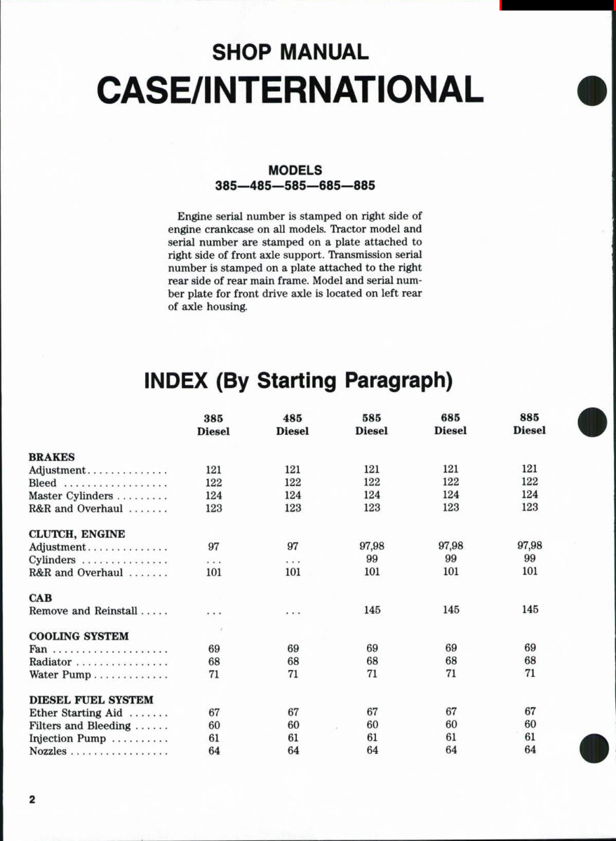
SHOP MANUAL CASE/INTERNATIONAL MODELS 385—485—585—685—885 Engine serial number is stamped on right side of engine crankcase on all models. Tractor model and serial number are stamped on a plate attached to right side of front axle support. Transmission serial number is stamped on a plate attached to the right rear side of rear main frame. Model and serial num- ber plate for front drive axle is located on left rear of axle housing. INDEX (By Starling Paragraph) BRAKES At^ustment Bleed Master Cylinders R&R and Overhaul CLUTCH, ENGINE Adjustment Cylinders R&R and Overhaul CAB Remove and Reinstall... COOLING SYSTEM Pan Radiator Water Pump DIESEL FXTEL SYSTEM Ether Starting Aid Filters and Bleeding Iiyection Pump Nozzles 385 Diesel 121 122 124 123 97 101 69 68 71 67 60 61 64 485 Die8el 121 122 124 123 97 101 69 68 71 67 60 61 64 585 Diesel 121 122 124 123 97,98 99 101 145 69 68 71 67 60 61 64 685 Diesel 121 122 124 123 97,98 99 101 145 69 68 71 67 60 61 64 885 Diesel 121 122 124 123 97,98 99 101 145 69 68 71 67 60 61 64
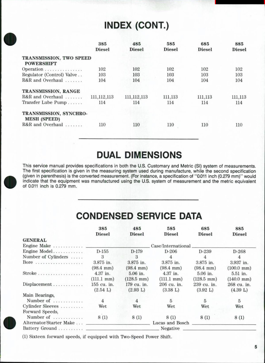
INDEX (CONT.) 385 Diesel TRANSMISSION, TWO SPEED POWERSHIFT Operation 102 Regulator (Control) Valve . . 103 R&R and Overhaul 104 TRANSMISSION, RANGE R&R and Overhaul 111,112,113 Transfer Lube Pump 114 TRANSMISSION, SYNCHRO- MESH (SPEED) R&R and Overhaul 485 Diesel 102 103 104 111,112,113 114 585 Diesel 102 103 104 111,113 114 685 Diesel 102 103 104 111,113 114 885 Diesel 102 103 104 111,113 114 110 no no no no DUAL DIMENSIONS This service manuai provides specifications in both the U.S. Customary and Metric (Si) system of measurements. The first specification is given in the measuring system used during manufacture, whiie the second specification (given in parenthesis) is the converted measurement. (For instance, a specification of **0.011 inch (0.279 mm)" would indicate that the equipment was manufactured using the U.S. system of measurement and the metric equivalent of 0.011 inch is 0.279 mm. CONDENSED SERVICE DATA 385 485 585 Diesel Diesel Diesel GENERAL Engine Make Case/International Engine Model D-155 D-179 D-206 Number of Cylinders 3 3 4 Bore 3.875 in. 3.875 in. 3.875 in. (98.4 mm) (98.4 mm) (98.4 mm) Stroke 4.37 in. 5.06 in. 4.37 in. (111.1 mm) (128.5 mm) (111.1 mm) Displacement 155 cu. in. 179 cu. in. 206 cu. in. (2.54 L) (2.93 L) (3.38 L) Main Bearings, Number of 4 4 5 Cylinder Sleeves Wet Wet Wet Forward Speeds, Number of 8(1) 8(1) 8(1) Alternator/Starter Make . . . Lucas and Bosch Battery Ground Negative (1) Sixteen forward speeds, if equipped with Two-Speed Power Shift. 685 Diesel D-239 4 3.875 in. (98.4 mm) 5.06 in. (128.5 mm) 239 cu. in. (3.92 L) 5 Wet 885 Diesel D-268 4 3.937 in. (100.0 mm) 5.51 in. (140.0 mm) 268 cu. in. (4.39 L) 5 8(1) 8(1)
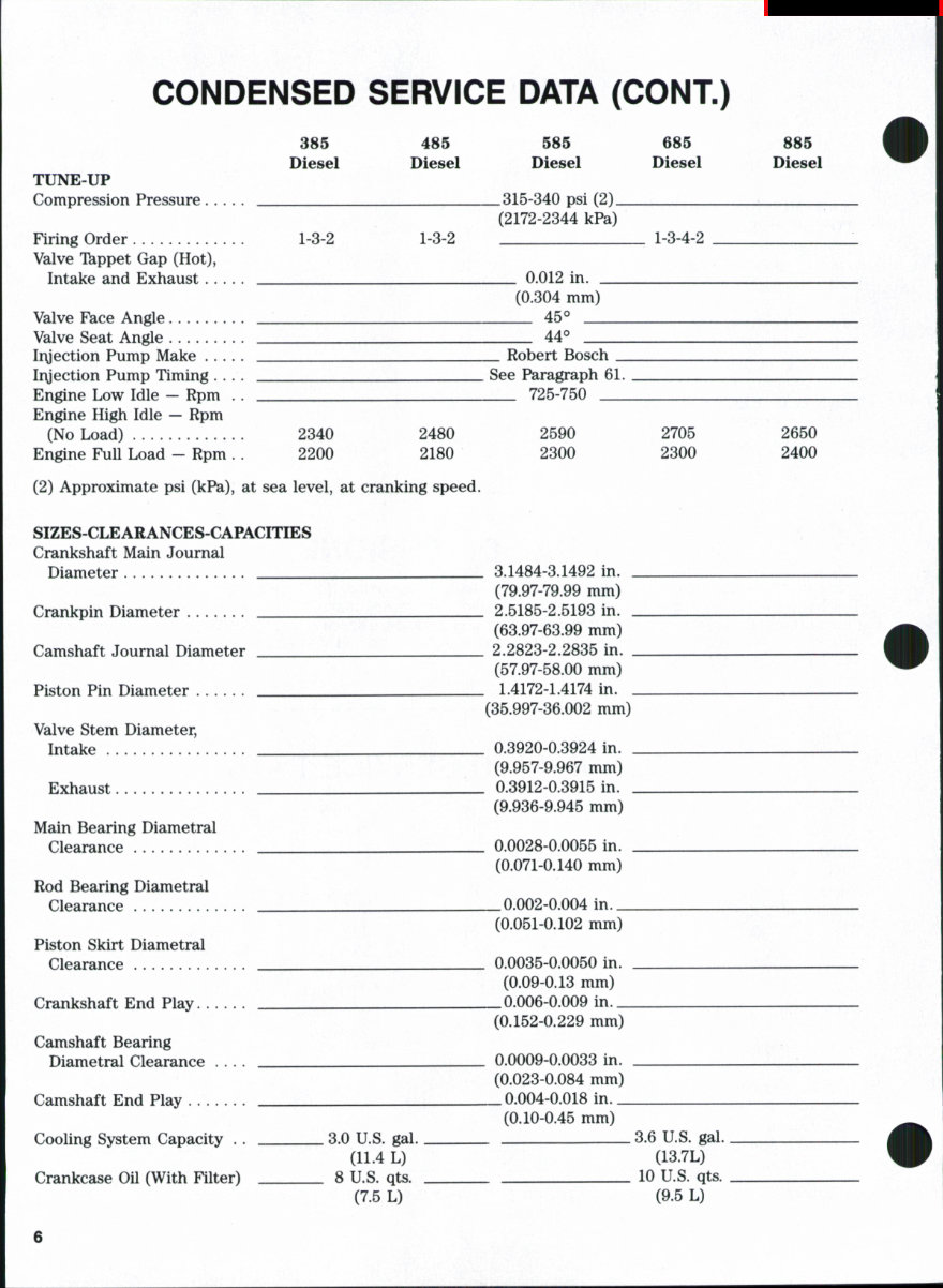
CONDENSED SERVICE DATA (CONT.) TUNE-UP Compression Pressure Firinc Order 385 Diesel 1-3-2 485 Diesel 1-3-2 585 Diesel 315-340 psi (2) (2172-2344 kPa) 685 Diesel 1-3-4-2 885 Diesel Valve Tkppet Gap (Hot), Intake and Exhaust Valve Face Angle Valve Seat Angle Ir\jection Pump Make Ir\jection Pump Timing .... Engine Low Idle — Rpm . . Engine High Idle — Rpm (No Load) 2340 2480 Engine Full Load — Rpm .. 2200 2180 (2) Approximate psi (kPa), at sea level, at cranking speed. 0.012 in. (0.304 mm) 45° 44° _ Robert Bosch _ See Paragraph 61. 725-750 2590 2300 2705 2300 2650 2400 SIZES-CLEARANCES-CAPACmES Crankshaft Main Journal Diameter Crankpin Diameter Camshaft Journal Diameter Piston Pin Diameter Valve Stem Diameter, Intake Exhaust Main Bearing Diametral Clearance . Rod Bearing Diametral Clearance Piston Skirt Diametral Clearance Crankshaft End Play Camshaft Bearing Diametral Clearance .... Camshaft End Play Cooling System Capacity . . Crankcase Oil (With Filter) . 3.0 U.S. gal. (11.4 L) . 8 U.S. qts. (7.5 L) . 3.1484-3.1492 in. _ (79.97-79.99 mm) . 2.5185-2.5193 in. _ (63.97-63.99 mm) . 2.2823-2.2835 in. _ (57.97-58.00 mm) _ 1.4172-1.4174 in. . (35.997-36.002 mm) . 0.3920-0.3924 in. . (9.957-9.967 mm) _ 0.3912-0.3915 in. _ (9.936-9.945 mm) . 0.0028-0.0055 in. . (0.071-0.140 mm) _0.002-0.004 in. _ (0.051-0.102 mm) 0.0035-0.0050 in. (0.09-0.13 mm) _ 0.006-0.009 in. _ (0.152-0.229 mm) 0.0009-0.0033 in. (0.023-0.084 mm) _ 0.004-0.018 in._ (0.10-0.45 mm) . 3.6 U.S. gal. (13.7L) . 10 U.S. qts. (9.5 L) 6
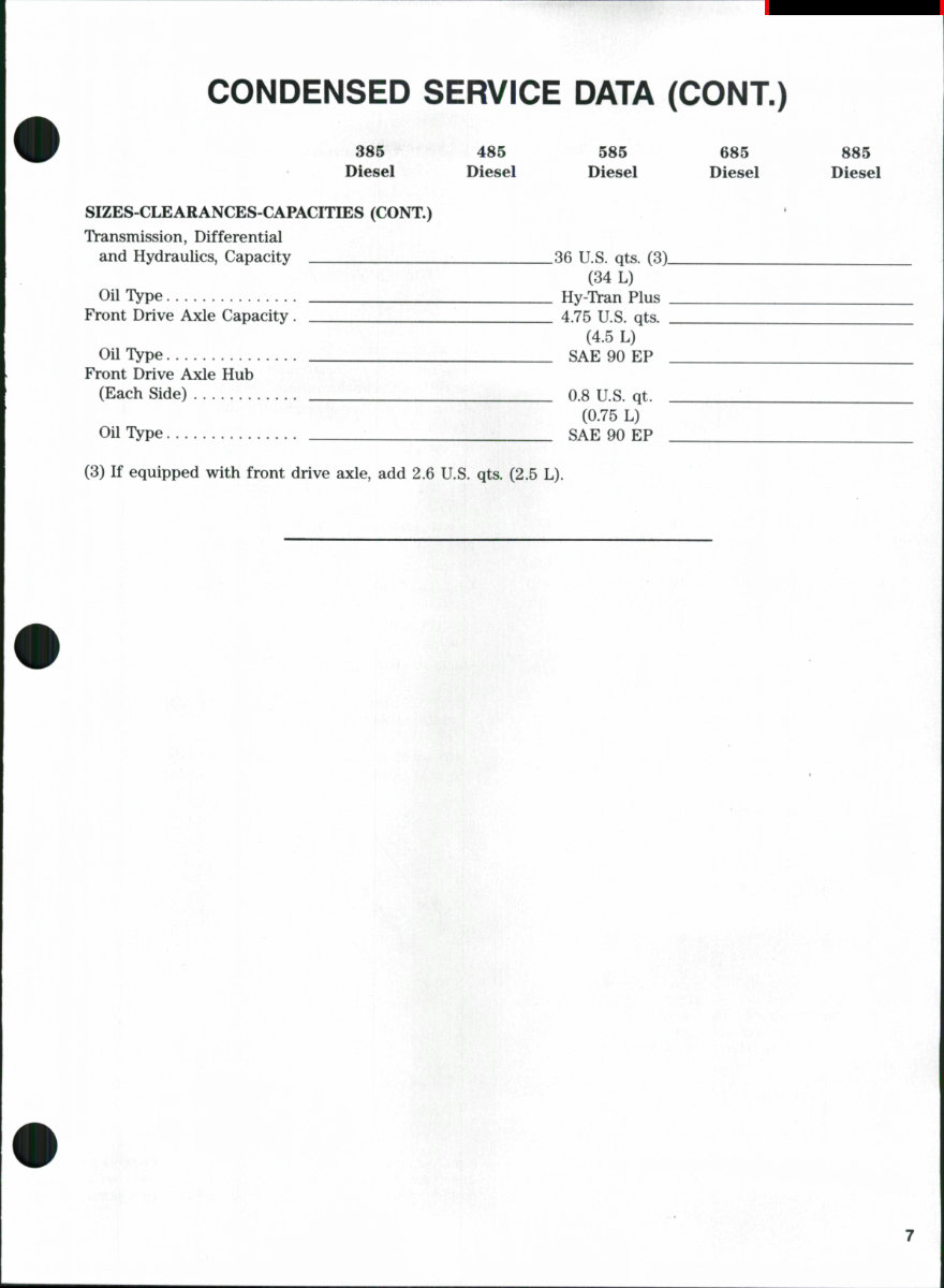
CONDENSED SERVICE DATA (CONT.) 385 485 585 685 885 Diesel Diesel Diesel Diesel Diesel SIZES-CLEARANCES-CAPACITIES (CONT.) Transmission, Differential and Hydraulics, Capacity 36 U.S. qts. (3) (34 L) Oil Type Hy-Tran Plus Front Drive Axle Capacity . 4.75 U.S. qts, (4.5 L) Oil Type SAE 90 EP Front Drive Axle Hub (Each Side) 0.8 U.S. qt. (0.75 L) Oil Type SAE 90 EP (3) If equipped with front drive axle, add 2.6 U.S. qts. (2.5 L).
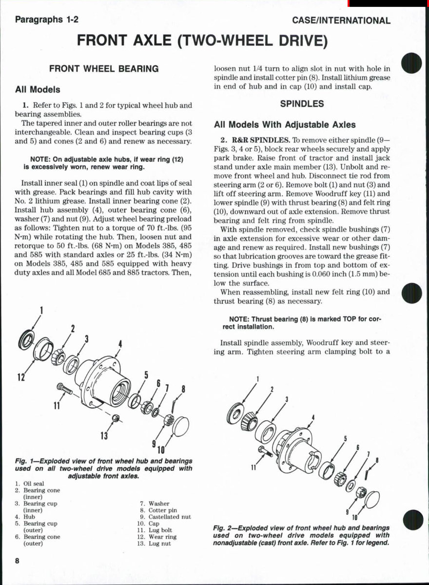
Paragraphs 1-2 CASE/INTERNATIONAL FRONT AXLE (TWO-WHEEL DRIVE) FRONT WHEEL BEARING All Models 1. Refer to Figs. 1 and 2 for typical wheel hub and bearing assemblies. The tapered inner and outer roller bearings are not interchangeable. Clean and inspect bearing cups (3 and 5) and cones (2 and 6) and renew as necessary. NOTE: On adjustable axle hubs, if wear ring (12) is excessiveiy worn, renew wear ring. Install inner seal (1) on spindle and coat lips of seal with grease. Pack bearings and fill hub cavity with No. 2 lithium gi^ease. Install inner bearing cone (2). Install hub assembly (4), outer bearing cone (6), washer (7) and nut (9). Adyust wheel bearing preload as follows: Tighten nut to a torque of 70 ft .-lbs. (95 N*m) while rotating the hub. Then, loosen nut and retorque to 50 ft.-lbs. (68 N-m) on Models 385, 485 and 585 with standard axles or 25 ft.-lbs. (34 N*m) on Models 385, 485 and 585 equipped with heavy duty axles and all Model 685 and 885 tractors. Then, 11 13 Fig. 1—Exploded view of front wheel hub and bearings used on all two-wheel drive models equipped with adjustable front axles. 1. Oil seal 2. Bearing cone (inner) 3. Bearing cup 7. Washer (inner) 8. Cotter pin 4. Hub 9. Castellated nut 5. Bearing cup 10. Cap (outer) 11. Lug bolt Bearing cone 12. Wear ring loosen nut 1/4 turn to align slot in nut with hole in spindle and install cotter pin (8). Install lithium grease in end of hub and in cap (10) and install cap. SPINDLES All Models With Adjustable Axles 2. R&R SPINDLES. Ib remove either spindle (9— Figs. 3, 4 or 5), block rear wheels securely and apply park brake. Raise front of tractor and install jack stand under axle main member (13). Unbolt and re- move front wheel and hub. Disconnect tie rod from steering arm (2 or 6). Remove bolt (1) and nut (3) and lift off steering arm. Remove Woodruff key (11) and lower spindle (9) with thrust bearing (8) and felt ring (10), downward out of axle extension. Remove thrust bearing and felt ring from spindle. With spindle removed, check spindle bushings (7) in axle extension for excessive wear or other dam- age and renew as required. Install new bushings (7) so that lubrication grooves are toward the grease fit- ting. Drive bushings in from top and bottom of ex- tension until each bushing is 0.060 inch (1.5 mm) be- low the surface. When reassembling, install new felt ring (10) and thrust bearing (8) as necessary. NOTE: Thrust bearing (8) is marked TOP for cor- rect instaiiation. Install spindle assembly. Woodruff key and steer- ing arm. Tighten steering arm clamping bolt to a (outer) 13. Lug nut Fig, 2—Exploded view of front wheel hub and bearings used on two-wheel drive models equipped with nonadjustable (cast) front axle. Refer to Fig. 1 for legend.
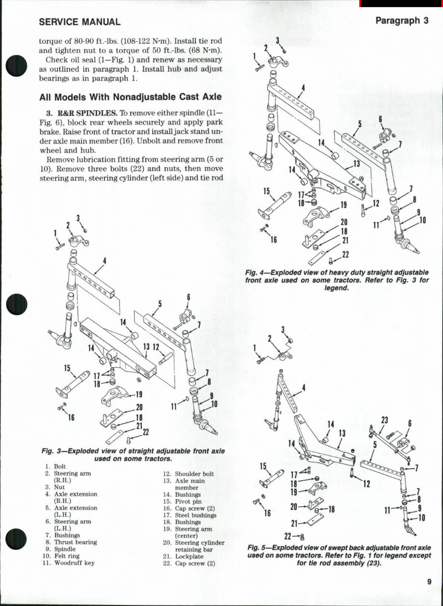
SERVICE MANUAL Paragraph 3 torque of 80-90 ft.-lbs. (108-122 N-m). Install tie rod and tighten nut to a torque of 50 ft.-lbs. (68 N*m). Check oil seal (1—Fig. 1) and renew as necessary as outlined in paragraph 1. Install hub and ac^ust bearings as in paragraph 1. All Models With Nonadjustable Cast Axie 3. R&R SPINDLES. To remove either spindle (11— Fig. 6), block rear wheels securely and apply park brake. Raise front of tractor and install jack stand un- der axle main member (16). Unbolt and remove front wheel and hub. Remove lubrication fitting from steering arm (5 or 10). Remove three bolts (22) and nuts, then move steering arm, steering cylinder (left side) and tie rod Fig. 3^Exploded view of straight adjustable front axle used on some tractors. 1. Bolt 2. Steering arm 12. Shoulder bolt (R.H.) 13. 3. Nut 4. Axle extension (R.H.) 5. Axle extension {L.H.) Steering arm (L.H.) Bushings Thrust bearing 20. Spindle 6. 7. 8. 9. 10. Felt ring 11. Woodruff key Axle main member Bushings 15. Pivot pin 16. Cap screw (2) 17. Steel bushings 18. Bushings Steering arm (center) Steering cylinder retaining bar Lockplate 14 19 Fig. 4—Exploded view of heavy duty straight adjustable front axle used on some tractors. Refer to Fig. 3 for legend. 21 22. Cap screw (2) 22-*i Fig. 5—Exploded view of swept back adjustable front axle used on some tractors. Refer to Fig. 1 for legend except for tie rod assembly (23). 9
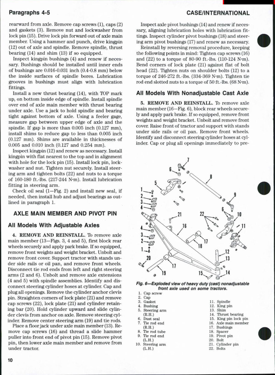
Paragraphs 4-5 CASE/iNTERNATiONAL rearward from axle. Remove cap screws (1), caps (2) and gaskets (3). Remove nut and lockwasher from lock pin (15). Drive lock pin forward out of axle main member Using a hammer and punch, drive kingpin (12) out of axle and spindle. Remove spindle, thrust bearing (14) and shim (13) if so equipped. Inspect kingpin bushings (4) and renew if neces- sary. Bushings should be installed until inner ends of bushings are 0.016-0.031 inch (0.4-0.8 mm) below the inside surfaces of spindle bores. Lubrication grooves in bushings must align with lubrication fittings. Install a new thrust bearing (14), with TOP mark up, on bottom inside edge of spindle. Install spindle over end of axle main member with thrust bearing under axle. Use a jack to hold spindle and bearing tight against bottom of axle. Using a feeler gage, measure gap between upper edge of axle and the spindle. If gap is more than 0.005 inch (0.127 mm), install shims to reduce gap to less than 0.005 inch (0.127 mm). Shims are available in thicknesses of 0.005 and 0.010 inch (0.127 and 0.254 mm). Inspect kingpin (12) and renew as necessary. Install kingpin with flat nearest to the top and in alignment with hole for the lock pin (15). Install lock pin, lock- washer and nut. Tighten nut securely. Install steer- ing arm and tighten bolts (22) and nuts to a torque of 160-180 ft.-lbs. (217-244 N-m). Install lubrication fitting in steering arm. Check oil seal (1—Fig. 2) and install new seal, if needed, then install hub and adjust bearings as out- lined in paragraph 1. AXLE MAiN MEMBER AND PiVOT PiN All Modeis With Adjustabie Axies 4. REMOVE AND REINSTALL. 1b remove axle main member (13—Figs. 3, 4 and 5), first block rear wheels securely and apply park brake. If so equipped, remove front weights and weight bracket. Unbolt and remove front cover. Support tractor with stands un- der side rails or oil pan, and remove front wheels. Disconnect tie rod ends from left and right steering arms (2 and 6). Unbolt and remove axle extensions (4 and 5) with spindle assemblies. Identify and dis- connect steering cylinder hoses at cylinder. Cap and plug all openings. Remove the cylinder anchor clevis pin. Straighten corners of lock plate (21) and remove cap screws (22), lock plate (21) and cylinder retain- ing bar (20). Hold cylinder upward and slide cylin- der clevis from anchor on axle. Remove steering cyl- inder. Remove center steering arm (19) and tie rods. Place a floor jack under axle main member (13). Re- move cap screws (16) and thread a slide hammer puller into front end of pivot pin (15). Remove pivot pin, then lower axle main member and remove from under tractor. Inspect axle pivot bushings (14) and renew if neces- sary, aligning lubrication holes with lubrication fit- tings. Inspect cylinder pivot bushings (18) and steer- ing arm pivot bushings (17) and renew as necessary. Reinstall by reversing removal procedure, keeping the following points in mind: Tighten cap screws (16) and (22) to a torque of 80-90 ft.-lbs. (110-124 N-m). Bend corners of lock plate (21) against flat of bolt head (22). Tighten nuts on shoulder bolts (12) to a torque of 246-272 ft.-lbs. (334-369 N-m). Tighten tie rod end slotted nuts to a torque of 50 ft.-lbs. (68 N-m). Aii Modeis With Nonadjustabie Cast Axle 5. REMOVE AND REINSTALL. Ib remove axle main member (16—Fig. 6), block rear wheels secure- ly and apply park brake. If so equipped, remove front weights and weight bracket. Unbolt and remove front cover. Raise front of tractor and support with stands under side rails or oil pan. Remove front wheels. Identify and disconnect steering cylinder hoses at cyl- inder. Cap or plug all openings immediately to pre- Fig. 6-—Exploded view of heavy duty (cast) nonadjustable front axle used on some tractors. 1. Cap screw 2. Cap Gasket 11. Spindle 3. 4. Bushing 5. Steering arm (R.H.) 6. Dust seal 7. Tie rod end (R.H.) 8. Tie rod tube 9. Tie rod end (L.H.) Steering arm (L.H.) 10 12. King pin 13. Shim 14. Thrust bearing 15. King pin lock pin 16. Axle main member 17. Bushings 18. Spacer 19. Pivot pin 20. Bolt 21. Cylinder pin 22. Bolts 10
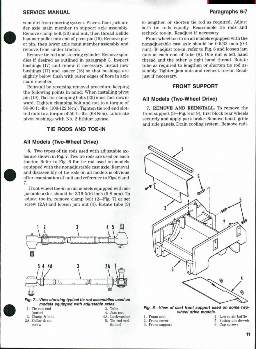
SERVICE MANUAL Paragraphs 6-7 vent dirt from entering system. Place a floor jack un- der axle main member to support axle assembly. Remove clamp bolt (20) and nut, then thread a slide hammer puller into end of pivot pin (19). Remove piv- ot pin, then lower axle main member assembly and remove from under tractor. Remove tie rod and steering cylinder Remove spin- dles if desired as outlined in paragraph 3. Inspect bushings (17) and renew if necessary. Install new bushings (17) and spacer (18) so that bushings are slightly below flush with outer edges of bore in axle main member Reinstall by reversing removal procedure keeping the following points in mind: When installing pivot pin (19), flat for clamping bolts (20) must fact down- ward. Tighten clamping bolt and nut to a torque of 80-90 ft.-lbs. (108-122 N-m). Tighten tie rod end slot- ted nuts to a torque of 50 ft.-lbs. (68 N-m). Lubricate pivot bushings with No. 2 lithium grease. TiE RODS AND TOE-iN to lengthen or shorten tie rod as required. Adjust both tie rods equally. Reassemble tie rods and recheck toe-in. Readjust if necessary. Front wheel toe-in on all models equipped with the nonadjustable cast axle should be 0-5/32 inch (0-4 mm). To adjust toe-in, refer to Fig. 6 and loosen jam nuts at each end of tube (8). One nut is left hand thread and the other is right hand thread. Rotate tube as required to lengthen or shorten tie rod as- sembly. Tighten jam nuts and recheck toe-in. Read- just if necessary. FRONT SUPPORT Aii Models (Two-Wheei Drive) 7. REMOVE AND REINSTALL. Tb remove the front support (3—Fig. 8 or 9), first block rear wheels securely and apply park brake. Remove hood, grille and side panels. Drain cooling system. Remove radi- All Modeis (Two-Wheei Drive) 6. Two types of tie rods used with adjustable ax- les are shown in Fig. 7. Two tie rods are used on each tractor. Refer to Fig. 6 for tie rod used on models equipped with the nonadjustable cast axle. Removal and disassembly of tie rods on all models is obvious after examination of unit and reference to Figs. 6 and 7. Front wheel toe-in on all models equipped with ad- justable axles should be 3/16-5/16 inch (5-8 mm). Ib adyust toe-in, remove clamp bolt (2—Fig. 7) or set screw (2A) and loosen jam nut (4). Rotate tube (3) Fig. 7—View showing typicai tie rod assembiies used on models equipped with adjustabie axies. 1. Tie rod end 3. Tube (outer) 4. Jam nut 2. Clamp & bolt 4A 2A. Collar & set screw Lockwasher 5. Tie rod end (inner) Fig. 8—View of cast front support used on some two- wheei drive models. 1. Foam seal 4. Lower air baffle 2. Front cover 5. Spring pin dowels 3. Front support 6. Cap screws 11
This is the Case IH 485 Service Repair Workshop Manual, a comprehensive guide containing full service and repair instructions utilized by mechanics worldwide.
It covers all major topics, providing step-by-step instructions, diagrams, illustrations, wiring schematics, and specifications for repairing and troubleshooting the Case IH 485.
Designed for both owners with basic mechanical skills and independent auto service professionals, this manual offers the same specifications and procedures available to authorized dealer service departments. Even car owners not intending to work on their vehicles will benefit from owning and referencing this manual, enabling them to be better informed and more knowledgeable when discussing repairs with automotive technicians.
The manual, written by the manufacturers, is designed to help with any necessary repairs and is suitable for both professional mechanics and DIY enthusiasts.
It is available in .PDF format, allowing viewing on PCs, Macs, and various devices including many phones and e-readers like the Amazon Kindle. The option to print individual pages as needed prevents the original from becoming obscured and unreadable due to oil stains.
Compatibility: All Versions of Windows and Mac
Printable: Yes
Language: English
Requirements: Adobe Reader
The manual includes pictures and easy-to-follow directions on required tools and repair procedures, potentially saving hundreds or thousands of dollars in repair bills by enabling simple repairs to be done independently.
It covers a wide range of topics including lubrication and maintenance, suspension, differential and driveline, brakes, cooling, audio/video, engine systems, and much more.
All pages are printable, making it convenient to take the necessary information into the garage or workshop, ultimately saving money by facilitating DIY repairs.
With very easy-to-follow, step-by-step instructions, this manual is suitable for individuals at any skill level.