

Case IH 2290 Workshop Repair Service Manual
What's Included?
Fast Download Speeds
Online & Offline Access
Access PDF Contents & Bookmarks
Full Search Facility
Print one or all pages of your manual
SHOP MANUAL
CASE/INTERNATIONAL
2090
MODELS ^
2290 2390 2590
2094 2294 2394 2594
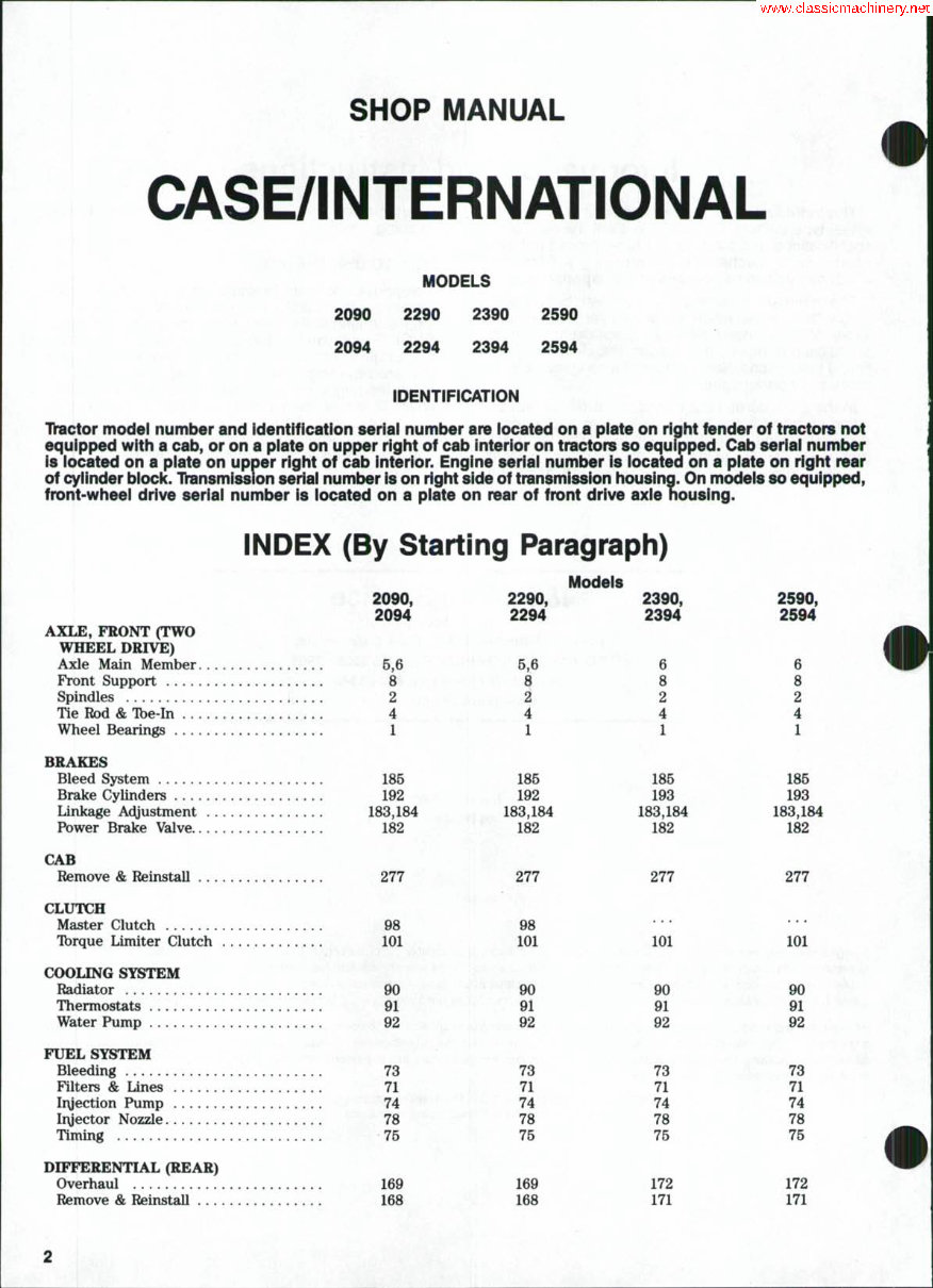
IDENTIFICATION
Thictor model number and Identification seriai number are iocated on a piate on right fender of tractors not
equipped with a cab, or on a piate on upper right of cab interior on tractors so equipped. Cab seriai number
is iocated on a piate on upper right of cab interior. Engine seriai number is iocated on a piate on right rear
of cyiinder block. Ihinsmission seriai number is on right side of transmission housing. On modeis so equipped,
front-wheei drive seriai number is iocated on a piate on rear of front drive axie housing.
INDEX (By Starting Paragraph)
2090,
2094
AXLE, FRONT (TWO
WHEEL DRIVE)
Axle Main Member 5,6
Front Support v .^^.
Spindles 2
Tie Rod & Tbe-In ,4
Wheel Bearings 1
BRAKES
Bleed System 185
Brake Cylinders 192
Linkage Adjustment 183,184
Power Brake Valve 182
CAB
Remove & Reinstall 277
CLUTCH
Master Clutch 98
Tbrque Umiter Clutch 101
COOLING SYSTEM
Radiator 90
Thermostats 91
Water Pump 92
FUEL SYSTEM
Bleeding 78
Filters & Lines 71
Iryection Pump 74
Iiyector Nozzle 78
Timing 75
DIFFERENTIAL (REAR)
Overhaul 169
Remove & Reinstall 168
2290,
2294
5,6
1
185
192
183,184
182
Models
2390,
2394
8
8
2
..4
1
186
193
183,184
182
2590,
2594
6
8
2
4
1
185
193
183,184
182
277 277 277
98
101
90
91
92
73
71
74
78
75
169
168
• • •
101
90
91
m
73
71
74
78
7B
172
171
* * *
101
• ' • ' , ' •
90
'' 91
92
73
71
74
78
75
172
171
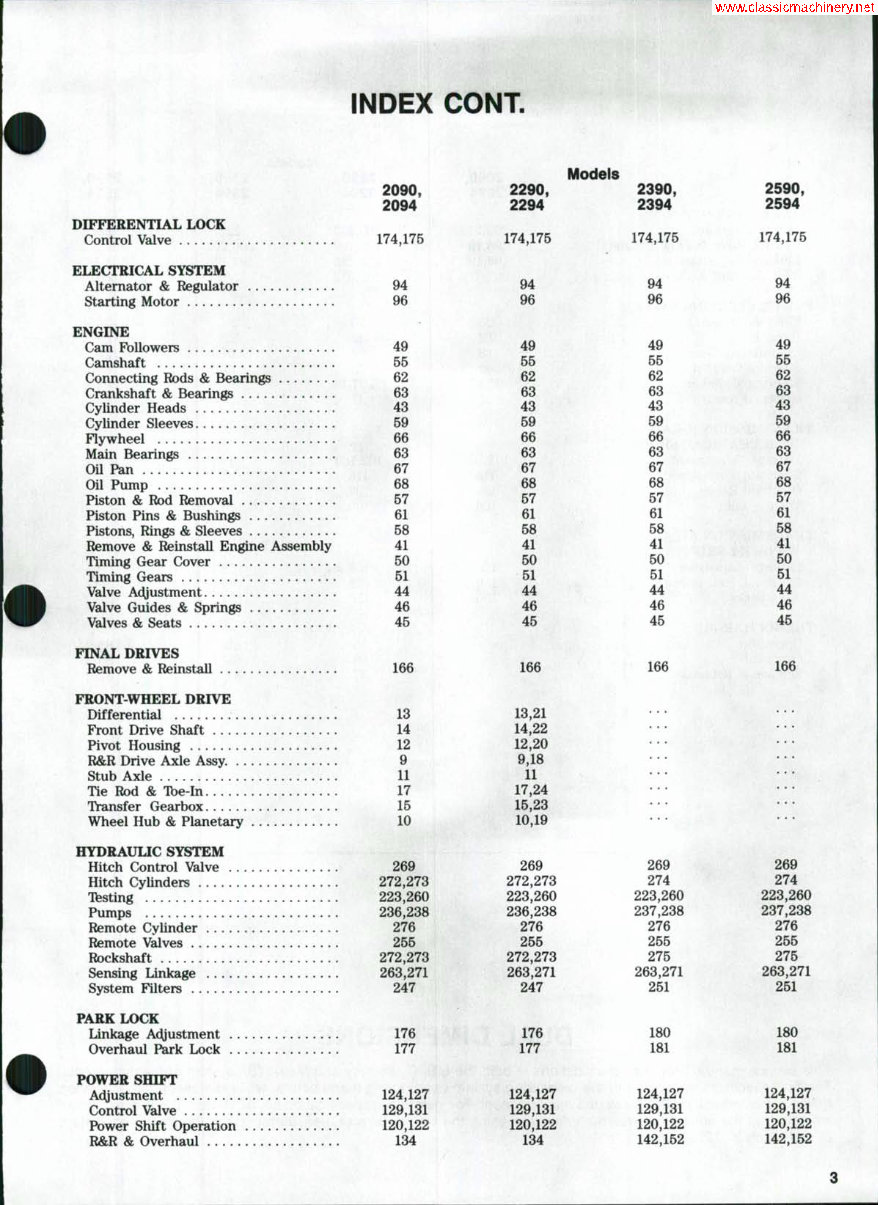
INDEX CONT.
DIFFERENTIAL LOCK
Control Valve
ELECTRICAL SYSTEM
Alternator & Regulator
Starting Motor
ENGINE
Cam Followers
Camshaft
Connecting Rods & Bearings
Crankshaft & Bearings
Cylinder Heads
Cylinder Sleeves
Flywheel
Main Bearings
Oil Pan
Oil Pump
Piston & Rod Removal
Piston Pins & Bushings
Pistons, Rings & Sleeves
Remove & Reinstall Engine Assembly
Timing Gear Cover
Timing Gears
Valve Adjustment
Valve Guides & Springs
Valves & Seats
FINAL DRIVES
Remove & Reinstall
FRONT-WHEEL DRIVE
Differential '.
Front Drive Shaft
Pivot Housing
R&R Drive Axle Assy.
Stub Axle
Tie Rod & Tbe-In
Transfer Gearbox
Wheel Hub & Planetary
HYDRAUUC SYSTEM
Hitch Control Valve
Hitch Cylinders
Testing
Pumps
Remote Cylinder
Remote Valves
Rockshaft
Sensing Linkage
System Filters
PARK LOCK
Linkage Adjustment
Overhaul Park Lock
POWER SHIFT
Ac^justment
Control Valve
Power Shift Operation
R&R & Overhaul
2090,
2094
174,175
94
96
49
55
62
63
43
59
66
63
67
68
57
61
58
41
50
51
44
46
45
166
13
14
12
9
11
17
15
10
269
272,273
223,260
236,238
276
255
272,273
263,271
247
176
177
124,127
129,131
120,122
134
Models
2290, 2390,
2294 2394
174,175
94
96
49
55
62
63
43
59
66
63
67
68
57
61
58
41
50
51
44
46
45
166
13,21
14,22
12,20
9,18
11
17,24
15,23
10,19
269
272,273
223,260
236,238
276
255
272,273
263,271
247
176
177
124,127
129,131
120,122
134
174,175
94
96
49
55
62
63
43
59
66
63
67
68
57
61
58
41
50
51
44
46
45
166
269
274
223,260
237,238
276
255
275
263,271
251
180
181
124,127
129,131
120,122
142,152
2590,
2594
174,175
94
96
49
55
62
63
43
59
66
63
67
68
57
61
58
41
50
51
44
46
45
166
269
274
223,260
237,238
276
255
275
263,271
251
180
181
124,127
129,131
120,122
142,152
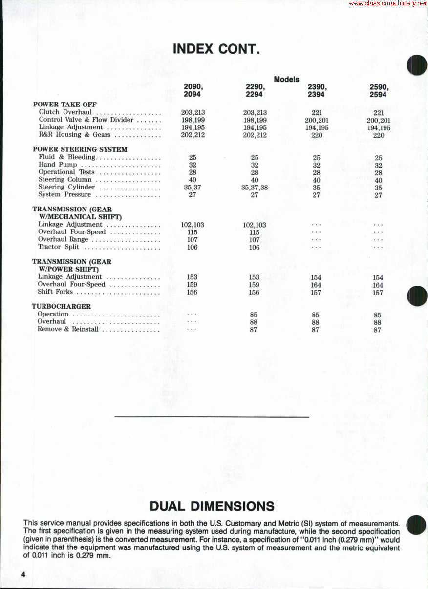
INDEX CONT.
POWER TAKE-OFF
Clutch Overhaul
Control Valve & Flow Divider
Linkage Ac^ustment
R&R Housing & Gears
POWER STEERING SYSTEM
Fluid & Bleeding
Hand Pump
Operational Tfests
Steering Column
Steering Cylinder
System Pressure
TRANSMISSION (GEAR
W/MECHANICAL SHIFT)
Linkage Adjustment
Overhaul Four-Speed
Overhaul Range
TVactor Split
TRANSMISSION (GEAR
W/POWER SHIFT)
Linkage Adjustment
Overhaul Four-Speed
Shift Forks
TURBOCHARGER
Operation
Overhaul
Remove & Reinstall
2090,
2094
203,213
198,199
194,195
202,212
25
32
28
40
35,37
27
102,103
115
107
106
153
159
156
2290,
2294
203,213
198,199
194,195
202,212
26
32
28
40
35,37,38
27
102,103
115
107
106
153
159
156
86
88
87
Models
2390,
2394
221
200,201
194,195
220
26
32
28
40
36
27
2590,
2594
221
200,201
194,195
220
25
32
28
40
35
27
154
164
157
85
88
87
154
164
157
m
m
87
DUAL DIMENSIONS
This service manual provides specifications in both the U.S. Customary and Metric (SI) system of measurements.
The first specification is given in the measuring system used during manufacture, while the second specification
(given in parenthesis) is the converted measurement. For instance, a specification of **0.011 inch (0.279 mm)" would
indicate that the equipment was manufactured using the U.S. system of measurement and the metric equivalent
of 0.011 inch is 0.279 mm.
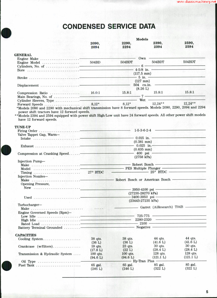
CONDENSED SERVICE DATA
Models
2090,
2094
2290,
2294
2390,
2394
2590,
2594
GENERAL
Engine Make " Own
Engine Model . 504BD 504BDT 504BDT 504BDT
Cylinders, No. of — 6
Bore — •— — 4-5/8 in.
(117.5 mm)
Stroke 5 in. —
(127 mm)
Displacement 504 cu.in. —
(8.26 L)
Compression Ratio 16.0:1 15.8:1 15.8:1 15.8:1
Main Bearings, No. of 7
Cylinder Sleeves, TVpe Wet
Fbrward Speeds 8,12* 8,12* 12,24** 12,24**
*Models 2090 and 2290 with mechanical shift transmission have 8 forward speeds. Models 2090, 2290, 2094 and 2294
power shift tractors have 12 forward speeds.
** Models 2394 and 2594 equipped with power shift High/Low unit have 24 forward speeds. All other power shift models
have 12 forward speeds.
TUNE-UP ' ' ' ''
Firing Order 1-5-3-6-2-4
Valve Tkppet Gap, Warm-
Intake —^ 0.015 in.
(0.381 mm)
Exhaust 0.025 in. —
(0.635 mm)
Compression at Cranking Speed —^ 400 psi
(2758 kPa)
Iryection P u m p -
Make Robert Bosch
Model PES Multiple Plunger
Timing 27*» BTDC 25*^ BTDC
Iryection Nozzles-
Make Robert Bosch or American Bosch
Opening Pressure,
^®^ • 3950-4100 psi
(27235-28270 kPa)
Used —3400-3950 psi —
(23443-27235 kPa)
": Garret (AiResearch) T04B
Engine Governed Speeds (Rpm)—
Low Idle 725-775
High Idle 2280-2320
Rated Load 2100
Battery Tferminal Grounded Negative
CAPACITIES
Cooling System 38 qts. 38 qts. 44 qts. 44 qts.
(36 L) (36 L) (41.6 L) (41.6 L)
Crankcase (w/filters) 19 qts. 23 qts. 30 qts. 30 qts.
(17.8 L) (22 L) (28.4 L) (28.4 L)
Transmission & Hydraulic System 100 qts. 100 qts. 128 qts. 128 qts.
(94.6 L) (94.6 L) (121.1 L) (121.1 L)
Oil Type Hy-Tran Plus
Fuel Tknk 65 gal. 65 gal. 85 gal. 85 gal.
(24G L) (246 L) (322 L) (322 L)
Paragraphs 1-5 CASE/INTERNATIONAL
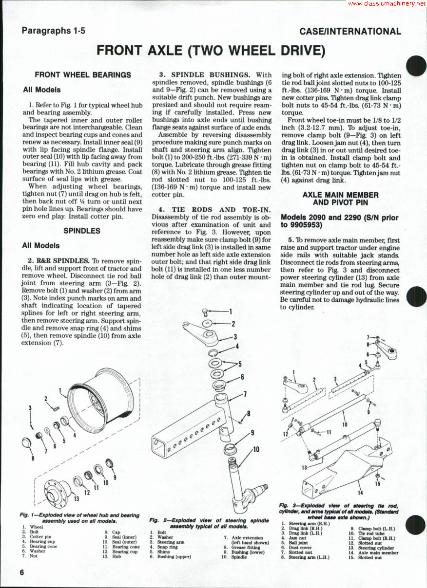
FRONT AXLE (TWO WHEEL DRIVE)
FRONT WHEEL BEARINGS
All Models '
1. Refer to Fig. 1 for typical wheel hub
and bearing assembly.
The tapered inner and outer roller
bearings are not interchangeable. Clean
and inspect bearing cups and cones and
renew as necessary. Install inner seal (9)
with lip facing spindle flange. Install
outer seal (10) with lip facing away from
bearing (11). Fill hub cavity and pack
bearings with No. 2 lithium grease. Coat
surface of seal lips with grease.
When adjusting wheel bearings,
tighten nut (7) until drag on hub is felt,
then back nut off Vi turn or until next
pin hole lines up. Bearings should have
zero end play. Install cotter pin.
SPINDLES
All Models
2. R&R SPINDLES. Ib remove spin-
dle, lift and support front of tractor and
remove wheel. Disconnect tie rod ball
joint from steering arm (3—Fig. 2).
Remove bolt (1) and washer (2) from arm
(3). Note index punch marks on arm and
shaft indicating location of tapered
splines for left or right steering arm,
then remove steering arm. Support spin-
dle and remove snap ring (4) and shims
(5), then remove spindle (10) from axle
extension (7).
3. SPINDLE BUSHINGS. With
spindles removed, spindle bushings (6
and 9—Fig. 2) can be removed using a
suitable drift punch. New bushings are
presized and should not require ream-
ing if carefully installed. Press new
bushings into axle ends until bushing
flange seats against surface of axle ends.
Assemble by reversing disassembly
procedure making sure punch marks on
shaft and steering arm align. Tighten
bolt (1) to 200-250 ft.'lbs. (271-339 N • m)
torque. Lubricate through grease fitting
(8) with No. 2 lithium grease. Tighten tie
rod slotted nut to 100-125 ft.-lbs.
(136-169 N • m) torque and install new
cotter pin.
4. TIE RODS AND TOE-IN.
Disassembly of tie rod assembly is ob-
vious after examination of unit and
reference to Fig. 3, However, upon
reassembly make sure clamp bolt (9) for
left side drag link (3) is installed in same
number hole as left side axle extension
outer bolt; and that right side drag link
bolt (11) is installed in one less number
hole of drag link (2) than outer mount-
Fig. 1—Exploded view of wheel hub and bearing
asaembly used on all model:
1. Wheel
2. Bolt 8. Cap
3. Cotter pin 9. Seal (inner)
4. Bearing cup 10. Seal (outer)
5. Bearing cone 11. Bearing cone
6. Washer 12. Bearing cup
7. Nut 13. Hub
Fig. 2—Exploded view of ateerlng aplndle
aaaembly typical of all modela.
1. Bolt
2. Washer 7. Axle extension
3. Steering arm (left hand shown)
4. Snap ring 8. Grease fitting
5. Shims Q. Bushing (lower)
6. Bushing (upper) 10. Spindle
ing bolt of right axle extension. Tighten
tie rod ball joint slotted nuts to 100-125
ft.-lbs. (136-169 N-m) torque. InstaU
new cotter pins. Tighten drag link clamp
bolt nuts to 45-54 ft.-lbs. (61-73 N • m)
torque.
Front wheel toe-in must be 1/8 to 1/2
inch (3.2-12.7 mm). 1b adjust toe-in,
remove clamp bolt (9—Fig. 3) on left
drag link. Loosen jam nut (4), then turn
drag link (3) in or out until desired toe-
in is obtained. Install clamp bolt and
tighten nut on clamp bolt to 45-54 ft.-
Ibs. (61-73 N • m) torque. Tighten jam nut
(4) against drag link.
AXLE MAIN MEMBER
AND PIVOT PIN
Models 2090 and 2290 (S/N prior
to 9905953)
5. Tb remove axle main member, first
raise and support tractor under engine
side rails with suitable jack stands.
Disconnect tie rods from steering arms,
then refer to Fig. 3 and disconnect
power steering cylinder (13) from axle
main member and tie rod lug. Secure
steering cylinder up and out of the way.
Be careful not to damage hydraulic lines
to cylinder.
12
15
14
Fig. 3^Exploded view of ateertng tie rod,
cylinder, and anrrn typical of all modele. (Standard
wheel baae axle ahown.}
1. steering ann (R.H.)
2. Drag link (R.H,)
3. Drag Unk (L.H.)
4. Jam nut
6. BaUJoint
6. Dust cover
7. Slotted nut
8. Steering ami (L.H.)
9. Clmmp bolt (L.H.)
10. Tie rod tube
11. Clamp bolt (R.H.)
12. Slotted nut
13. Steering cylinder
14. Axle main member
15. Slotted nut
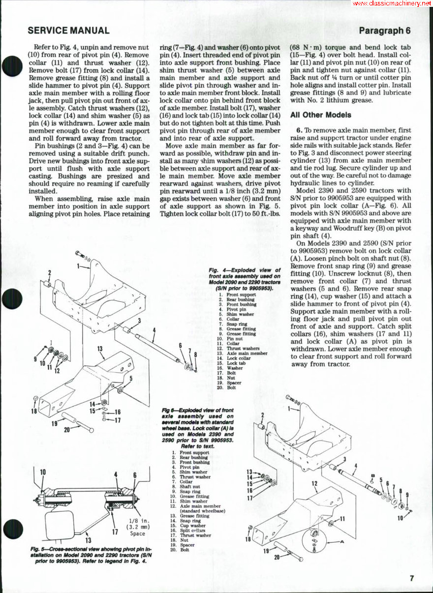
SERVICE MANUAL Paragraph 6
Refer to Fig. 4, unpin and remove nut
(10) from rear of pivot pin (4). Remove
collar (11) and thrust washer (12).
Remove bolt (17) from lock collar (14).
Remove grease fitting (8) and install a
slide hammer to pivot pin (4). Support
axle main member with a rolling flo(»r
jack, then pull pivot pin out front of ax-
le assembly. Catch thrust washers (12),
lock collar (14) and shim washer (5) £is
pin (4) is withdrawn. Lower axle main
member enough to clear front support
and roll forward away from tractor.
Pin bushings (2 and 3—Fig. 4) can be
removed using a suitable drift puncli.
Drive new bushings into front axle sup-
port until flush with axle suppoit
casting. Bushings are presized and
should require no reaming if carefully
installed.
When assembling, raise axle main
member into position in axle support
aligning pivot pin holes. Place retairiing
ring (7—Fig. 4) and washer (6) onto pivot
pin (4). Insert threaded end of pivot pin
into axle support front bushing. Place
shim thrust washer (5) between axle
main member and axle support and
slide pivot pin through washer and in-
to axle main member front block. Install
lock collar onto pin behind front block
of axle member. Install bolt (17), washer
(16) and lock tab (15) into lock collar (14)
but do not tighten bolt at this time. Push
pivot pin through rear of axle member
and into rear of axle support.
Move axle main member as far for-
ward as possible, withdraw pin and in-
stall as many shim washers (12) as possi-
ble between axle support and rear of ax-
le main member. Move axle member
rearward against washers, drive pivot
pin rearward until a 1/8 inch (3.2 mm)
gap exists between washer (6) and front
of axle support as shown in Fig. 5.
Tighten lock collar bolt (17) to 60 ft.-lba
Ftg. 4—Exploded W«iv of
front ax/e a999mbfy u—d on
Mod0l 2090 and 2290 tncton
(S/N prior to 990S9S9h
1. Front support
2. Rear bufliUng
3. Front bushing
^ 4. Pivot pin
5. Shim washer
'" \ 6. Collar
'. 7. Snap ring
: 8. Grease fitting
9. Grease fitting
10. Pin nut
11. Collar
12. Thrust washers
13. Axle main member
14. Lock collar
16. Lock tab
16. Washer
17. Bolt
18. Nut
19. Spacer
20. Bolt
(68 N-m) torque and bend lock tab
(15—Fig. 4) over bolt head. Install col-
lar (11) and pivot pin nut (10) on rear of
pin and tighten nut against collar (11).
Back nut off V4 turn or until cotter pin
hole aligns and install cotter pin. Install
grease fittings (8 and 9) and lubricate
with No. 2 lithium grease.
All Other Models
6. Tb remove axle main member, first
raise and support tractor under engine
side rails with suitable jack standa Refer
to Fig. 3 and disconnect power steering
cylinder (13) from axle main member
and tie rod lug. Secure cylinder up and
out of the way. Be careful not to damage
hydraulic lines to cylinder.
Model 2390 and 2590 tractors with
S/N prior to 9905953 are equipped with
pivot pin lock collar (A—Fig. 6). All
models with S/N 9905953 and above are
equipped with axle main member with
a keyway and Woodruff key (B) on pivot
pin shaft (4).
On Models 2390 and 2590 (S/N prior
to 9905953) remove bolt on lock collar
(A). Loosen pinch bolt on shaft nut (8).
Remove front snap ring (9) and grease
fitting (10). Unscrew locknut (8), then
remove front collar (7) and thrust
washers (5 and 6). Remove rear snap
ring (14), cup washer (15) and attach a
slide hammer to front of pivot pin (4).
Support axle main member with a roll-
ing floor jack and pull pivot pin out
front of axle and support. Catch split
collars (16), shim washers (17 and 11)
and lock collar (A) as pivot pin is
withdrawn. Lower axle member enough
to clear front support and roU forward
away from tractor.
20
whaal baaa. Lock collar (A) la
uaad on Modala 2390 and
2590 prior to S/N 9905953.
1.
n A.
3.
4.
5.
6.
7.
8.
9.
10.
11.
12.
13.
14.
16.
16.
17.
18.
19.
20.
Rafar to taxt.
Front support
Front bushing
Pivot pin
Shim washer
Thrust washer
Collar
Shaft nut
Snap dng
Grease fitting
Shim washer
Axle main member
(standard wheelbase)
Grease fitting
Snap ring
Cup washer
Split collars
Thrust washer
Nut
Spacer
Bolt >
13
14
15
16
17
11
r
/-, 18'
atallaHon on Modal 2090 and 2290 tractora (S/H
prior to 990$953}. Rafar to lagand In Fig. 4.
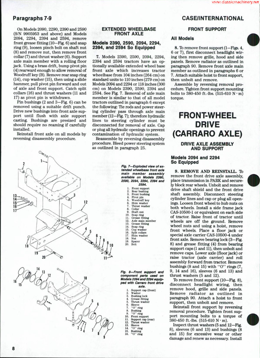
Paragraphs 7-9 CASE/INTERNATIONAL
On Models 2090, 2290, 2390 and 2590
(S/N 9905953 and above) and Models
2094, 2294, 2394 and 2594, remove
front grease fitting (10—Fig. 6) and snap
ring (9), loosen pinch bolt on shaft nut
(8) and remove nut, then remove front
collar (7) and thrust washer (6). Support
axle main member with a rolling floor
jack. Using a brass drift, bump pivot pin
(4) rearward enough to allow removal of
Woodruff key (B). Remove rear snap ring
(14), cup washer (15), then using a slide
hammer, pull pivot pin forward and out
of axle and front support. Catch split
collars (16) and thrust washers (11 and
17) as pivot pin is withdrawn.
Pin bushings (2 and 3—Fig. 6) can be
removed using a suitable drift punch.
Drive new bushings into front asde sup-
port until flush with axle support
casting. Bushings are presized and
should require no reaming if carefuUy
installed.
Reinstall front axle on all models by
reversing disassembly procedure.
EXTENDED WHEELBASE
FRONT AXLE
Models 2390, 2590, 2094, 2294,
2394, and 2594 So Equipped
7. Models 2390, 2590, 2094, 2294,
2394 and 2594 tractors have an op-
tionally available extended wheel base
front axle which increases tractor
wheelbase from 104 inches (264 cm) on
standard units to 110 inches (279 cm) on
Models 2094 and 2294 or 118 inches (300
cm) on Models 2390, 2590, 2394 and
2594. See Fig. 7. Removal of axle main
member is similar to that of all model
tractors outlined in paragraph 6 except
the following: Tie rods and power steer-
ing cylinder pass through axle main
member (12—Fig. 7); therefore hydraulic
lines to steering cylinder must be
disconnected for removal of axle. Cap
or plug all hydraulic openings to prevent
contamination of hydraulic system.
Reassemble by reversing disassembly
procedure. Bleed power steering system
as outlined in paragraph 25.
Fig. 7—Exploded view of ex-
tended wheeltmae front axle
main member assembly
available on Models 2390,
2590, 2094, 2294, 2394 and
2S94.
1. Front support
2. Rear bushing
3. Front bushing
4. Pivot pin
5. Woodruff key
6. Shim washer
7. Thrust washer
8. Collar
0. Shaft nut
10. Snap ring
11. Grease fitting
12. Axle main member
13. Grease fitting
14. Snap ring
16. Cup washer
16. SpUt collars
17. Shint washer
18. Nut
19. Spacer
20. Bolt
Fig, 8—Front support and
component parts used on
Models 2094 and 2294 equip-
ped with Carraro front drive
axle.
1. Support cap (front)
2. Washer
3. Bushing lock
4. Grease fltting
6. Thrust washer
6. Sleeve
7. "O" ring
8. Bushing
9. "O" ring
10. Front support
11. Support cap (rear)
12. Thrust washer
13. Sleeve
14. "0" ring
16. Bushing
16. " 0 " ring
FRONT SUPPORT
All Models
8. Tb remove front support (1—Figs. 4,
6 or 7), first disconnect headlight wir-
ing then remove grille, hood and side
panels. Remove radiator as outlined in
paragraph 90. Remove front axle main
member as outlined in paragraphs 6 or
7. Attach suitable hoist to front support,
then unbolt and remove.
Assemble by reversing removal pro-
cedure. Tighten front support mounting
bolts to 380-450 ft.-lbs. (515-610 N • m)
torque.
FRONT-WHEEL
DRIVE
(CARRARO AXLE)
DRIVE AXLE ASSEMBLY
AND SUPPORT
Models 2094 and 2294
So Equipped
9. REMOVE AND REINSTALL. Tb
remove the front drive axle assembly,
place transmission in PARK and secure-
ly block rear wheels. Unbolt and remove
drive shaft shield and the front drive
shaft assembly. Disconnect steering
cylinder lines and cap or plug all open-
ings. Loosen front wheel to hub nuts on
both wheels. Install a side frame jack
CAS-10500-1 or equivalent on each side
of tractor. Raise front of tractor until
wheels are off the ground. Remove
wheel nuts and using a hoist, remove
front wheels. Place a floor jack or
special axle carrier CAS-10500-4 under
front axle. Remove bearing lock (3—Fig.
8) and grease fittiiig (4) from bearing
support caps (1 and 11), then unbolt and
remove caps. Lower axle (floor jack) or
raise tractor (axle carrier) and roll
assembly forward from tractor. Remove
bushings (8 and 15) with *'O** rings (7,
9, 14 and 16), sleeves (6 and 13) and
thrust washers (5 and 12).
Ib remove front support (10—Fig. 8),
disconnect headlight wiring, then
remove hood, grille and side panels.
Remove radiator as outlined in
paragraph 90. Attach a hoist to front
support, then unbolt and remove.
Reinstall front support by reversing
removal procedure. Tighten front sup-
port mounting bolts to a torque of
380-450 ft.-lbs. (515-610 N • m).
Inspect thrust washers (5 and 12—Fig.
8), sleeves (6 and 13) and bushings (8
and 15) for excessive wear or other
damage and renew as necessary. Install
SERVICE MANUAL Paragraphs 10-11
sleeves (6 and 13) on axle housing, then
install thrust washers (5 and 12).
Lubricate sleeves and install bushings (8
and 15) with new '*0*' rings. Reinstall
axle assembly to front support (10). In-
stall support caps (1 and 11), maldng cer-
tain the lube holes in bushings are
aligned with holes in caps. Tighten sup-
port cap nuts to a torque of 400-480 ft.-
lbs. (542-650 N • m). Install bushing locks
(3) and grease fittings (4). Connect steer-
ing cylinder hoses and drive shaft.
Tighten drive shaft bolts to a torque of
35-42 ft.-lbs. (48-57 N • m). InstaU driv<?
shaft shield. Install front wheels and
remove jacks. Tighten front wheel to
hub nuts to 400-480 ft.-lbs. (542-650
N • m) torque.
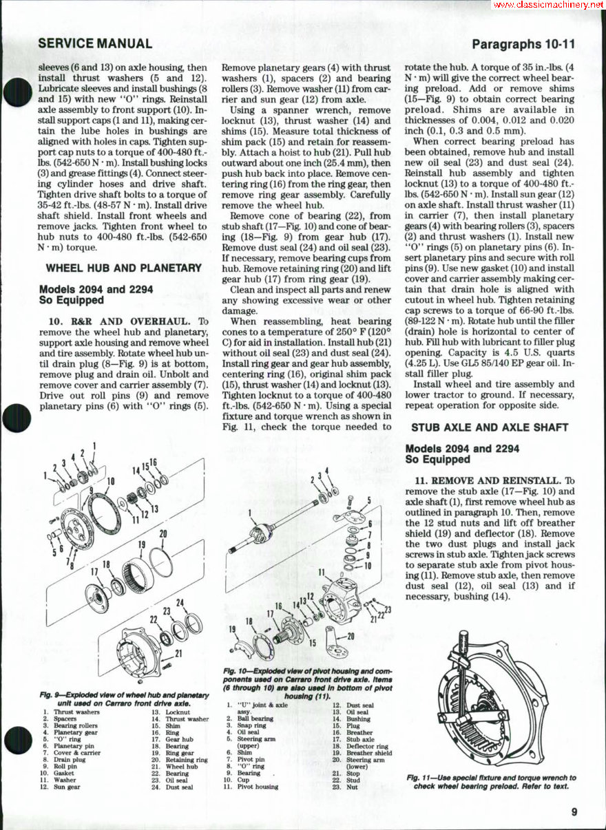
WHEEL HUB AND PLANETARY
Models 2094 and 2294
So Equipped
10. R&R AND OVERHAUL. TD
remove the wheel hub and planetarj^,
support axle housing and remove wheel
and tire assembly. Rotate wheel hub un-
til drain plug (8—Fig. 9) is at bottom,
remove plug and drain oil. Unbolt an<l
remove cover and carrier assembly (7).
Drive out roll pins (9) and remove
planetary pins (6) with *'O'* rings (5).
Fig. 9—Exploded view of wheel hub and planeiary
unit ueed on Cerrmro front drive axle.
1. Thrust washers 13. Locknut
2. Spacers 14. Thrust wa^er
3. Beuing rollers 16. Shim
4. Planetary geu- 16. Ring
5. "O" ring 17. Gear hub
6. Planetary pin 18. Bearing
7. Cover A earner 19. Ring gear
8. Drain plug 20. Retaining ring
9. HoU pin 21. Wheel hub
10. Gasket 22. Bearing
11. Washer 23. OU seal
12. Sun gear 24. Dust seal
Remove planetary gears (4) with thrust
washers (1), spacers (2) and bearing
rollers (3). Remove washer (11) from car-
rier and sun gear (12) from axle.
Using a spanner wrench, remove
locknut (13), thrust washer (14) and
shims (15). Measure total thickness of
shim pack (15) and retain for reassem-
bly. Attach a hoist to hub (21). Pull hub
outward about one inch (25.4 mm), then
push hub back into place. Remove cen-
tering ring (16) from the ring gear, then
remove ring gear assembly. Carefully
remove the wheel hub.
Remove cone of bearing (22), from
stub shaft (17—Fig. 10) and cone of bear-
ing (18—Fig. 9) from gear hub (17).
Remove dust seal (24) and oil seal (23).
If necessary, remove bearing cups from
hub. Remove retaining ring (20) and lift
gear hub (17) from ring gear (19).
Clean and inspect all parts and renew
any showing excessive wear or other
damage.
When reassembling, heat bearing
cones to a temperature of 250° F (120*^
C) for aid in installation. Install hub (21)
without oil seal (23) and dust seal (24).
Install ring gear and gear hub assembly,
centering ring (16), original shim pack
(15), thrust washer (14) and locknut (13).
Ti^ten locknut to a torque of 400-480
ft.-lbs. (542-650 N • m). Using a special
fixture and torque wrench as shown in
Fig. 11, check the torque needed to
Rg, lO—Exploded view of pivot houeing end com-
ponente ueed on Carrero front drive axle. Iteme
($ through 10) are also used In t>ottom of pivot
housing (11).
1. "U" Joint A axle 12. Dust seal
assy. 13. Oil seal
2. BaU bearing 14. Bushing
3. Snap ring 15. Plug
4. OUseal 16. Breather
5. Steering arm 17. Stub axle
(upper) IB. Deflector ring
6. Shim 19. Breather shield
7. Pivot pin 20. Steering arm
8. "O" ring (lower)
9. Bearing . 21. Stop
10. Cup 22. Stud
11. Pivot housing 23. Nut
rotate the hub. A torque of 35 in.-lba (4
N • m) will give the correct wheel bear-
ing preload. Add or remove shims
(15—Fig. 9) to obtain correct bearing
preload. Shims are available in
thicknesses of 0.004, 0.012 and 0.020
inch (0.1, 0.3 and 0.5 mm).
When correct bearing preload has
been obtained, remove hub and install
new oil seal (23) and dust seal (24).
Reinstall hub assembly and tighten
locknut (13) to a torque of 400-480 ft.-
lbs. (542-650 N • m). InstaU sun gear (12)
on axle shaft. Install thrust washer (11)
in carrier (7), then install planetary
gears (4) with bearing rollers (3), spacers
(2) and thrust washers (1). Install new
'*0'* rings (5) on planetary pins (6). In-
sert planetary pins and secure with roll
pins (9). Use new gasket (10) and install
cover and carrier assembly making cer-
tain that drain hole is aligned with
cutout in wheel hub. Tighten retaining
cap screws to a torque of 66-90 ft.-lbs.
(89-122 N • m). Rotate hub untU the filler
(drain) hole is horizontal to center of
hub. Fin hub with lubricant to filler plug
opening. Capacity is 4.5 U.S. quarts
(4.25 L). Use GL5 85/140 EP gear oU. In-
staU filler plug.
Install wheel and tire assembly and
lower tractor to ground. If necessary,
repeat operation for opposite side.
STUB AXLE AND AXLE SHAFT
Models 2094 and 2294
So Equipped
11. REMOVE AND REINSTALL. Tb
remove the stub axle (17—Fig. 10) and
axle shaft (1), first remove wheel hub as
outlined in paragraph 10. Then, remove
the 12 stud nuts and lift off breather
shield (19) and deflector (18). Remove
the two dust plugs and install jack
screws in stub axle. Tighten jack screws
to separate stub axle from pivot hous-
ing (11). Remove stub axle, then remove
dust seal (12), oil seal (13) and if
necessary, bushing (14).
Fig. 11—Uee special fixture and torque wrench to
check wheel bearing preload. Refer to text.
Paragraphs 12-13 CASE/INTERNATIONAL
Remove upper and lower hole plugs at
outer end of axle housing, then loosen
locknuts and remove bearing locating
screws. Withdraw axle shaft assembly.
Remove snap ring (3) and bearing (2). Oil
seal (4) can be pulled from axle hous-
ing, if desired. All parts for the double
'*U'* joint axle shaft are available
separately. Procedures for renewing
"U" joint crosses and bearings are
conventional.
When reassembling, install oil seal (4)
with lip facing inward. Install bearing (2)
and secure with snap ring (3). Lubricate
oil seal (4) and carefully install axle
shaft (1). Install and tighten upper and
lower bearing locating screws. TTien, in-
stall locknuts and tighten to a torque of
195 ft.lbs. (264 N • m).
If removed, install new bushing (14)
in stub axle. Install new oil seal (13), but
DO NOT bottom in bore. Install dust seal
(12) until flush with face of bore.
Lubricate seals and install stub axle,
deflector (18) and breather shield (19).
Install stud nuts and tighten to a torque
of 203 ft.lbs. (275 N • m).
Reinstall wheel hub as outlined in
paragraph 10. . -
PIVOT HOUSING
Models 2094 and 2294
So Equipped
12. REMOVE AND REINSTALL. Tb
remove the pivot housing (11—Fig. 10),
first remove wheel hub as in paragraph
10 and stub axle and axle shaft as in
paragraph 11. Then, disconnect steering
cylinder from upper steering arm (5)
and tie rod from lower steering arm (20).
Unbolt and remove lower steering arm
(20) and lower shims (6). Attach a slide
hammer to lower pivot pin (7) and
remove pivot pin and bearing cone. Un-
bolt and remove upper steering arm (5)
and upper shims (6). Using a slide ham-
mer, remove upper pivot pin (7) and
bearing cone. lift off pivot housing (11).
If necessary, use a slide hammer puller
to remove bearing cups from axle
housing.
Clean and inspect all parts and renew
as necessary. Heat bearing cones to 250°
F (120*=* C) for aid in installation. Allow
to cool and install new '*0'* rings (8). If
removed, install bearing cups in axle
housing. Pack bearing cones with grease
and put grease in cups (10) in axle hous-
ing. Install pivot housing and insert
pivot pins and bearing cones. Use a
plastic hammer and tap pivot pins into
position. Install lower steering arm (20)
without shims and tighten cap screws to
a torque of 30 ft.-lbs. (40 N • m). Place
all the shims (6) removed from upper
and lower pivot pins plus another shim
of 0.020 inch (0.5 mm) thickness on the
upper pivot pin. Install upper steering
arm (5) and tighten cap screws to a
torque of 30 ft.-lbs. (40 N • m). Using a
feeler gage, measure the distance be-
tween upper steering arm and ma-
chined surface on pivot housing.
Remove upper steering arm and all
shims. Measure shim pack thickness.
Subtract shims equal to the measured
distance between steering arm and
pivot housing from shim pack. Divide
remaining shims by two. Place each
shim pack half plus an additional
0.006-0.008 inch (0.15-0.20 mm) shim
under each steering arm to provide
0.012-0.016 inch (0.3-0.4 mm) total bear-
ing preload. Tighten upper and lower
steering arm cap screws to a torque of
317 ft.-lbs. (430 N • m).
Complete balance of installation by
reversing the removal procedure.
DIFFERENTIAL AND
BEVEL DRIVE GEARS
Models 2094 and 2294
So Equipped
13. R&R AND OVERHAUL. Ib
remove the differential assembly, first
remove front drive axle assembly as
outlined in paragraph 9. Then, remove
wheel hubs and planetarys as in
paragraph 10 and stub axles and axle
shafts as in paragraph 11. Remove steer-
ing cylinders and tie rod. Remove drain
plug and drain lubricant from axle hous-
ing. Attach a hoist to differential carrier,
then unbolt and remove differential
assembly.
NOTE: It may be necessary to use |ack
screws to force differential carrier from ax-
le housing.
Place assembly on a bench and
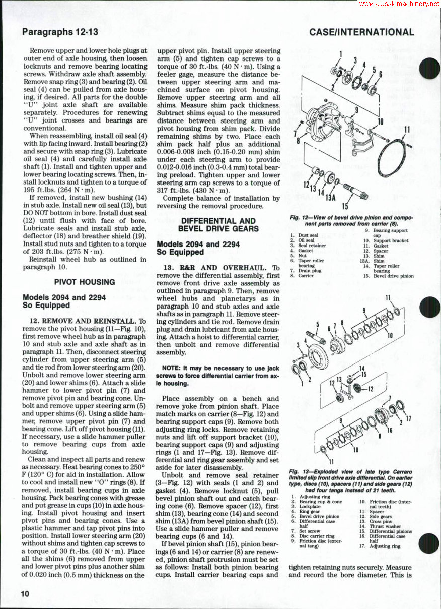
remove yoke from pinion shaft. Place
match marks on carrier (8—Fig. 12) and
bearing support caps (9). Remove both
adjusting ring locks. Remove retaining
nuts and lift off support bracket (10),
bearing support caps (9) and adjusting
rings (1 and 17—Fig. 13). Remove dif-
ferential and ring gear assembly and set
aside for later disassembly.
Unbolt and remove seal retainer
(3—Fig. 12) with seals (1 and 2) and
gasket (4). Remove locknut (5), pull
bevel pinion shaft out and catch bear-
ing cone (6). Remove spacer (12), first
shim (13), bearing cone (14) and second
shim (13A) from bevel pinion shaft (15).
Use a slide hammer puller and remove
bearing cups (6 and 14).
If bevel pinion shaft (15), pinion bear-
ings (6 and 14) or carrier (8) are renew-
ed, pinion shaft protrusion must be set
as follows: Install both pinion bearing
cups. Install carrier bearing caps and
12
13
14
Fig. 12—View of bevel drive pinion and compo-
nent parts removed from carrier (8).
9. Bearing support
1. Dust seal cap
2. Oil seal 10. Support bracket
3. Seal retainer U. Gasket
4. Gasket 12. Spacer
B. Nut 13. Shim
6. Taper roller 13A. Shim
bearing 14. Taper roller
7. Drain plug bearing
8. Carrier 15. Bevel drive pinion
Fig. 13—Exploded view of late type Carrara
limited slip front drive axle differential. On earlier
type, discs (10), spacers (11) and side gears (12)
had four tangs Instead of 21 teeth.
1. Adjusting ring
2. Bearing cup & cone 10. Friction disc (inter-
3. Lockplate nal teeth)
4. Ring gear 11. Spacer
5. Bevel drive pinion 12. Side gears
6. Differential case 13. Cross pins
half 14. Thrust washer
7. Set screw 15. Differential pinions
8. Disc carrier ring 16. EHfferential case
9. Friction disc (exter- half
nal tang) 17. Adjusting ring
tighten retaining nuts securely. Measure
and record the bore diameter. This is
10
SERVICE MANUAL Paragraph 14
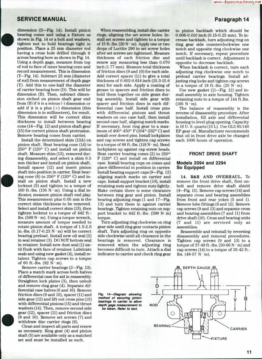
dimension (D—Fig. 14). Install pinion
bearing cones and using a fixture as
shown in Fig. 14 or a bolt and washers,
tighten nut to hold bearings tight in
position. Place a 25 mm diameter rod
having a cross hole drilled through it
across bearing bore as shown in Fig. 14.
Using a depth gage, measure from top
of rod to face of inner bearing cone and
record measurement. This is dimension
(Y—Fig. 14). Subtract 25 mm (diameter
of rod) from measurement of depth gage
(Y). Add this to one-half the diameter
of carrier bearing bore (D). This will be
dimension (B). Then, subtract dimen-
sion etched on pinion shaft gear end
from fB) if it is a minus f-l dimension or
add if it is a plus (+) dimension (this
dimension is in millimeters), for result.
This dimension wiU be correct shim
thickness to install between bearing
cone (14—Fig. 12) and pinion shaft gear
(15) for correct pinion shaft protrusion.
Remove bearing cones from carrier.
Install the determined shim (13A) on
pinion shaft. Heat bearing cone (14) to
250° F (120*^ C) and install on pinion
shaft. Measure shim (13), removed dur-
ing disassembly, and select a shim 0,5
mm thicker and install on pinion shaft.
Install spacer (12) and insert pinion
shaft into position in carrier. Heat bear-
ing cone (6) to 250° F (120° C) and in-
stall on pinion shaft. Install a new
locknut (5) and tighten to a torque of
100 ft.-lbs. (135 N • m). Using a dial in-
dicator, measure pinion shaft end play.
This measurement plus 0.05 mm is the
correct shim thickness to be removed.
Select and install correct shim (13), then
tighten locknut to a torque of 442 ft.-
lbs. (599 N • m). Using a torque wrench,
measure amount of torque needed to
rotate pinion shaft. A torque of 1.5-2.0
in.-lbs. (0.17-0.23 N • m) will be correct
bearing preload. Install new oil seal (2)
in seal retainer (3). DO NOT bottom sejil
in retainer. Install new dust seal (1) un-
til fiush with face of retainer. Lubricate
seals and using new gasket (4), install n;-
tainer. Tighten cap screws to a torque
of 60 ft.-lbs. (82 N • m).
Remove carrier bearings (2—Fig. 13).
Place a match mark across both halveis
of differential case for aid in reassembly.
Straighten lock plates (3), then unbolt
and remove ring gear (4). Separate dif-
ferential case halves (6 and 16). Remove
friction discs (9 and 10), spacer (11) and
side gear (12) and lift out cross pins (13)
with differential pinions (15) and thrust
washers (14). Then, remove second side
gear (12), spacer (11) and friction discs
(9 and 10). Remove set screws (7) and
withdraw disc carrier rings (8).
Clean and inspect all parts and renew
as necessary. Ring gear (4) and pinion
shaft (5) are available only as a matched
set and must be installed as such.
When reassembling, install disc carrier
rings, aligning the set screw holes. In-
stall set screws and tighten to a torque
of 15 ft.-lbs. (20 N • m). Apply one or two
drops of Loctite 290 in set screw holes
after set screws are tightened. Measure
thickness of each friction disc and
renew any measuring less than 0.070
inch (1.77 mm). Measure total thickness
of friction discs (9 and 10) for each side.
Add correct spacer (11) to give a total
thickness of 0.602-0.614 inch (15.3-15.6
mm) for each side. Apply a coating of
grease to spacers and friction discs to
hold them together on side gears dur-
ing assembly. Install side gear with
spacer and friction discs in each dif-
ferential case half. Install cross pins
with differential pinions and thrust
washers on one case half, then install
second case half, aligning match marka
If necessary, heat ring gear to a max-
imum of 400°-450° F(204°-232° C) and
install over dowel pins. Install lockplates
and cap screws and tighten cap screws
to a torque of 88 ft.-lbs. (119 N • m). Bend
lockplates up against cap screw heads.
Heat carrier bearing cones (2) to 250°
F (120° C) and install on differential
case. Install bearing cups on cones and
place differential in position in carrier.
InstaU bearing support caps (9—Fig. 12)
aligning match marks on carrier and
caps. Install support bracket (10), install
retaining nuts and tighten nuts lightly.
Make certain there is some clearance
between ring gear and pinion. Install
bearing adjusting rings (1 and 17—Fig.
13) and turn them in against carrier
bearings. Tighten retaining nuts on sup-
port bracket to 442 ft.-lbs. (599 N m)
torque.
Turn adjusting ring clockwise on ring
gear side until ring gear contacts pinion
shaft. Turn adjusting ring on opposite
side clockwise until all clearance in the
bearings is removed. Clearance is
removed when the acyusting ring
becomes difficult to turn. Attach a dial
indicator to carrier and check ring gear
to pinion backlash which should be
0.006-0.010 inch (0.15-0.25 mm). Tb in-
crease backlash, turn ac^usting ring on
ring gear side counterclockwise one
notch and opposite ring clockwise one
notch. If necessary, repeat procedure
until backlash is correct. At^justment is
opposite to decrease backlash.
When backlash is correct, turn each
adjusting ring clockwise one notch to
preload carrier bearings. Install ad-
justing ring locks and tighten cap screws
to a torque of 18 ft.-lbs. (25 N • m).
Use new gasket (11—Fig. 12) and in-
stall assembly in axle housing. Tighten
retaining nuts to a torque of 144 ft.lbs.
(195 N • m).
The balance of reassembly is the
reverse of disassembly procedure. After
installation, fill axle and differential
housing to level plug opening. Capacity
is 16 U S. quarts (15 L). Use GL5 85/140
EP gear oil. Manufacturer recommends
that oil in front drive axle be changed
each 1000 hours of operation.
FRONT DRIVE SHAFT
Models 2094 and 2294
So Equipped
14. R&R AND OVERHAUL. TD
remove the front drive shaft, first un-
bolt and remove drive shaft shield
(4—F^. 15). Remove cap screws (14) and
separate cross and bearing assemblies
from front and rear yokes (5 and 1).
Remove lube fittings (8 and 12). Remove
cap screws (9 and 13) and separate cross
and bearing assemblies (7 and 11) from
drive shaft (10). Cross and bearing units
(7 and 11) are serviced only as
assemblies.
Reassemble and reinstall by reversing
disassembly and removal procedures.
Tighten cap screws (9 and 13) to a
torque of 37-49 ft.-lbs. (50-66 N • m) and
cap screws (14) to a torque of 35-42 ft.-
lbs. (48-57 N • m).
Fig. 14—Dlagram showing
method of securing pinion
bearings In carrier to allow
depth gage measurement to
be taken. Refer to text.
ROD
BEARING
CARRIER
IXTURE
11
You're Reading a Preview
What's Included?
Fast Download Speeds
Online & Offline Access
Access PDF Contents & Bookmarks
Full Search Facility
Print one or all pages of your manual
$31.99
Viewed 52 Times Today


Secure transaction
What's Included?
Fast Download Speeds
Online & Offline Access
Access PDF Contents & Bookmarks
Full Search Facility
Print one or all pages of your manual
$31.99
This professional technical manual contains service, maintenance, and troubleshooting information for your Case IH 2290, covering all models, engines, trim, and transmission types. It is useful for both professional mechanics and DIY enthusiasts.
The manual includes detailed information on the following:
- Case IH 2290 Engine
- Case IH 2290 Lubrication System
- Case IH 2290 Cooling System
- Case IH 2290 Fuel System
- Case IH 2290 Disassembly and Servicing
- Case IH 2290 General
- Case IH 2290 Separation
- Case IH 2290 Clutch
- Case IH 2290 Transmission
- Case IH 2290 Drive Chain & Sprockets
- Case IH 2290 Rear Axle
- Case IH 2290 Brakes
- Case IH 2290 Front Axle
- Case IH 2290 Steering
- Case IH 2290 Shocks
- Case IH 2290 Body Work
- Case IH 2290 Intake & Exhaust
- Case IH 2290 Hydraulic System
- Case IH 2290 Electrical System
- Case IH 2290 Routine Maintenance
- Case IH 2290 Advanced Troubleshooting
- Case IH 2290 Wiring Diagram
This manual is available in electronic format, allowing for easy access and printing of specific sections for use during repairs or services. It contains step-by-step repair procedures, critical specifications, illustrations, maintenance, disassembly, assembly, cleaning, and reinstalling procedures.
Product Details:
- File Format: PDF
- Language: English
- Specifications: Full Printable
- Zoom IN/OUT: Yes
- Delivery: Instant
- Requirements: Adobe Reader & WinZip
- Compatible: All Versions of Windows & Mac
Instant delivery means no shipping cost or waiting for the book or CD to arrive in the mail.


