1-1 SECTION 1 ENGINE CONTENTS INTRODUCTION 1-2 ..................................................................... AIR INDUCTION SYSTEM - DESCRIPTION AND OPERATION 1-3 ............................ AIR INDUCTION SYSTEM - SPECIFICATIONS 1-8 ......................................... AIR INDUCTION SYSTEM - REMOVAL AND REPAIR OF COMPONENTS 1-9 .................. AIR INDUCTION SYSTEM - REPAIR TIME FOR INDIVIDUAL COMPONENTS 1-29 ............. EXHAUST SYSTEM - DESCRIPTION AND OPERATION 1-30 ................................ EXHAUST SYSTEM - SPECIFICATIONS 1-33 .............................................. EXHAUST SYSTEM - REMOVAL AND REPAIR OF COMPONENTS 1-34 ...................... EXHAUST SYSTEM - REPAIR TIME FOR INDIVIDUAL COMPONENTS 1-48 ................... ENGINE - DESCRIPTION AND OPERATION 1-49 ........................................... ENGINE - SPECIFICATIONS 1-51 ......................................................... ENGINE - TROUBLESHOOTING 1-53 ..................................................... ENGINE - ADJUSTMENTS 1-57 ........................................................... ENGINE - REMOVAL AND REPAIR OF COMPONENTS 1-68 ................................. ENGINE - REPAIR TIME FOR INDIVIDUAL COMPONENTS 1-140 ............................ COOLING SYSTEM - DESCRIPTION AND OPERATION 1-141 ............................... COOLING SYSTEM - SPECIAL TOOLS 1-146 .............................................. COOLING SYSTEM - SPECIFICATIONS 1-147 .............................................. COOLING SYSTEM - TROUBLESHOOTING AND TESTING 1-148 ............................ COOLING SYSTEM - REMOVAL AND REPAIR OF COMPONENTS 1-154 ..................... COOLING SYSTEM - REPAIR TIME FOR INDIVIDUAL COMPONENTS 1-177 ..................
SECTION 1 - ENGINE 1-2 INTRODUCTION The engine section of this manual is broken into four separate sections: S air induction system S exhaust system S engine removal and installation S cooling system The Buhler Versatile 4WD tractors use a diesel engine manufactured for Buhler Versatile by the Cummins Engine Company and are available in five different sizes with five different horsepower outputs. The following chart is a list of tractor models with horsepower and engine classification: Model Engine Horsepower Engine Type 2240 C8.3 240 Mechanical 2270 M11 270 Mechanical 2310 M11 310 Mechanical 2360 N14 360 Electronic 2425 N14 425 Electronic If an internal engine problem arises, that requires engine removal, this section will describe the proper procedure for removal and installation of the engine assembly. The engine will be repaired by an authorized Cummins dealer/distributor. When contact is made with your Cummins dealer/distributor, it is important that the information contained on the Engine Identification Plate is given. On the 2270 and 2310 (Cummins M11) engines, the Engine Identification Plate is located on the left side of the engine block below the valve cover. For the 2240 (Cummins C8.3) and 2360 and 2425 (Cummins N14) tractors, the Engine Identification Plate is located on the left side of the engine ahead of the fuel injection pump. NOTE: It is very important to include the engine number, engine family, and engine CPL (control parts listing) number when contacting your Cummins Engine Dealer/Distributor. To locate your nearest Cummins Engine Dealer/Distributor, contact the Cummins Engine Co. at 1-800 DIESELS (North America, excluding Alaska and Hawaii).
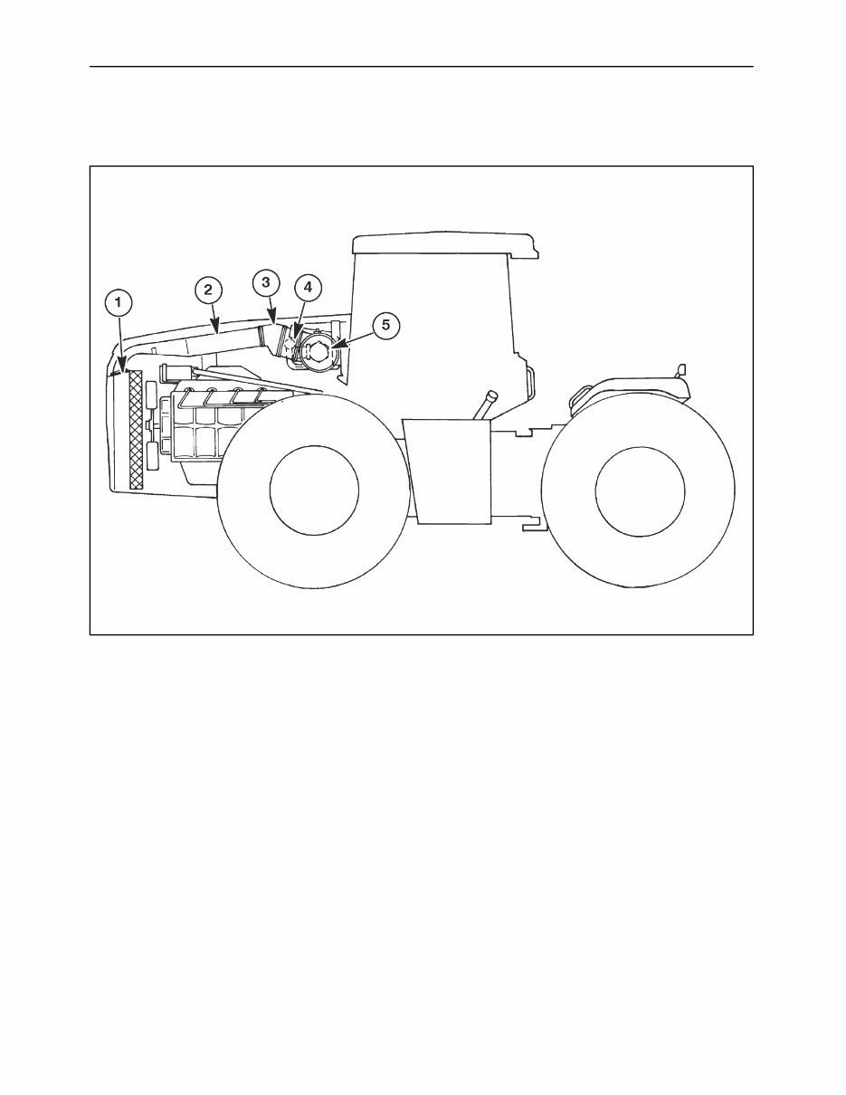
SECTION 1 - ENGINE 1-3 AIR INDUCTION SYSTEM - DESCRIPTION AND OPERATION Figure 1-1 INTRODUCTION The air induction system is the first section to be covered in the engine section. The air induction system has slight variations for the different engines supplied by the Cummins Engine Company. Though there are a few variations, the components are the same, for all Buhler Versatile 4WD tractors. The air induction system consists of a bulb seal, 1, surrounding the front edge of the air induction tube (Some early production tractors may not have the bulb seal installed. If not, install a seal at the time of service.); the air induction tube, 2, is mounted to the upper radiator shell and directs fresh air to the rubber boot, 3. The rubber boot is connected to the precleaner, 4. The precleaner is designed to eliminate larger particles of dirt and debris from entering into the air cleaner, 5. The air cleaner is comprised of a primary (outer) air filter and a secondary (inner) air filter to ensure that no dirt or debris reaches, and damages, the turbocharger assembly. The air cleaner is mounted to the rear engine frame by four bolts. Their are eight bolt holes on later production tractors to accommodate orientation of air induction components. When installing the air cleaner, be certain to mount it in the proper holes or the air induction components will not fit the tractor properly.
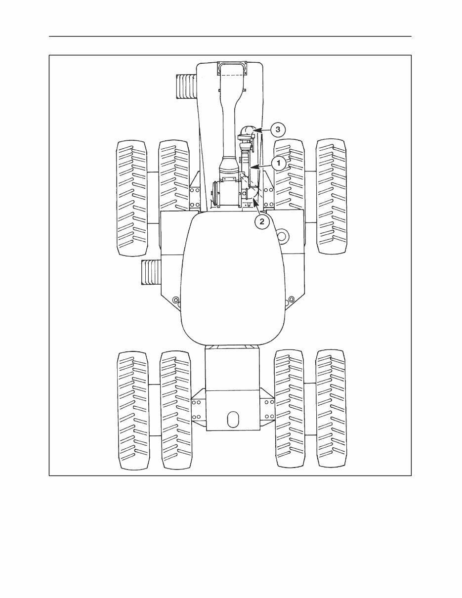
SECTION 1 - ENGINE 1-4 Figure 1-2 An overview of the air induction system incorporates the pipe work running from the air cleaner to the turbocharger on the right hand side of the engine compartment. The steel tube, 1, is mounted on a rubber boot, 2, where it connects to the air cleaner and a second rubber boot where it connects to the turbocharger, 3. There will be a slight difference in the size and position of the steel tube running to the turbocharger depending upon the engine being repaired. The removal and installation procedure is the same for all engines.
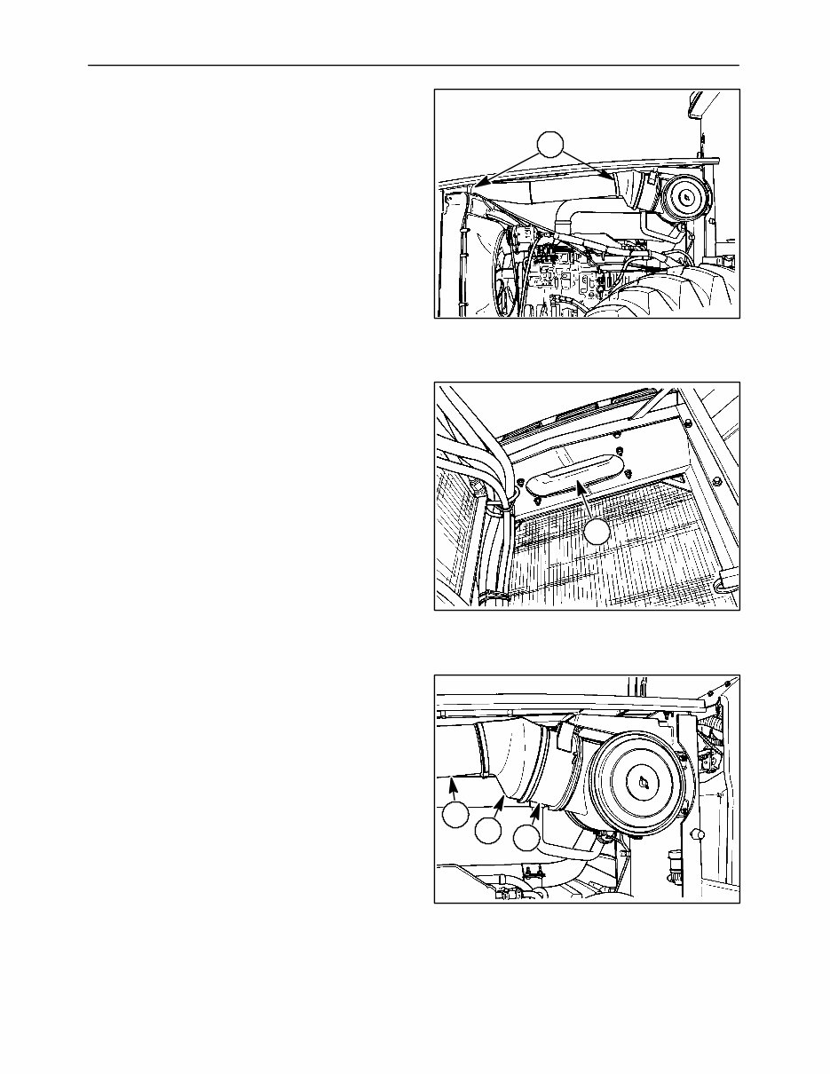
SECTION 1 - ENGINE 1-5 INDIVIDUAL COMPONENT OPERATION Air Induction Tube The air induction tube, 1, is mounted above the engine assembly, under the engine hood and directs fresh air from the front of the tractor to the engine. The air induction tube connects to a rubber boot with hose clamps. The front opening of the air induction tube is mounted to the upper radiator shell of the tractor to allow cooler air to enter the system. The opening is covered with a bulb seal, 1. Some early production tractors did not have the bulb seal installed. If the tractor does not have a bulb seal, install one at the time of service. Rubber Boot The rubber boot, 1, of the air induction system connects the air induction tube, 2, to the precleaner, 3. 1 Figure 1-3 1 Figure 1-4 1 2 3 Figure 1-5
SECTION 1 - ENGINE 1-6 Precleaner The precleaner, 1, for the air induction system is located behind the rubber boot, 2, and before the engine air cleaner, 3. The precleaner has a honeycomb shaped element used to remove dirt from the air and will discharge it through the muffler. Cleaning of the precleaner is required every 500 hours to insure their is no obstruction of air flow to the inner and outer air filters in the air cleaner. Air Cleaner The cylinder shaped air cleaner, 1, is mounted to the rear hood support and to the precleaner, 2. The air cleaner element houses the inner and outer air filters. The air filters are easily accessible by removing the wing nut, 3, and cover plate, 4, on the left hand side of the air cleaner. For additional information on the servicing of the air filters see your operators manual for specific instructions. NOTE: Do not service the inner or outer air filters unless the warning lamp on the dash is illuminated. 1 3 2 Figure 1-6 1 4 3 2 Figure 1-7
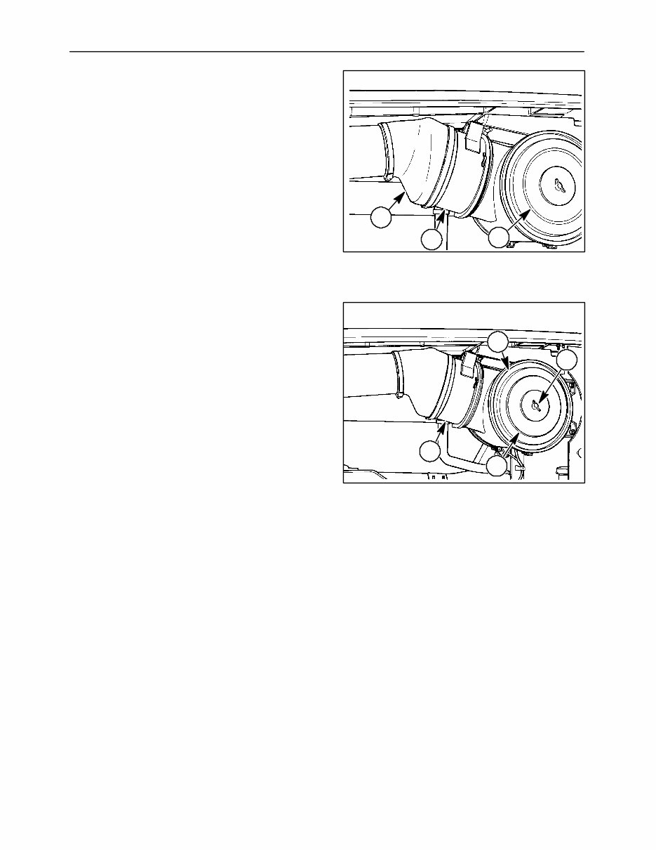
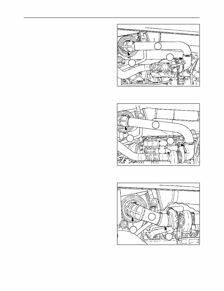
SECTION 1 - ENGINE 1-7 Air Cleaner to Turbocharger Pipe Work The air cleaner to turbocharger pipe work delivers clean fresh air from the air cleaner element to the turbocharger. Inspect the clamps and fittings periodically to ensure proper operation of the turbocharger. 2240 (C8.3) air cleaner to turbo pipe work: 1 - Rubber boot 2 - Steel tube 3 - Rubber boot 2270 and 2310 (M11) air cleaner to turbo pipe work: 1 - Rubber boot 2 - Steel tube 3 - Rubber boot 2360 and 2425 (N14) electronic air cleaner to turbo pipework: 1 - Rubber boot 2 - Steel tube 3 - Rubber boot 3 1 2 Figure 1-8 3 1 2 Figure 1-9 3 1 2 Figure 1-10
SECTION 1 - ENGINE 1-8 AIR INDUCTION SYSTEM - SPECIFICATIONS Buhler Versatile 4WD AIR INTAKE 2240 2270 2310 2360 2425 Air Intake Precleaner Exhaust Aspirated with Precleaner Air Filter Configuration Primary (Outer) Secondary (Inner) Air flow cmm (cfm) @ 2100 rpm 18.7 (660) 23.2 (820) 23.2 (820) 30.4 (1075) 31.1 (1100)
This workshop service manual for the Buhler Versatile 2310 tractor is designed for mechanical technicians familiar with service procedures for BRP products. It covers repair and overhaul of the Buhler Versatile 2310 tractor, assuming the technician is well-versed in general automobile practices. The manual includes instructions on components manufactured for the tractor, as well as repairs of proprietary components. It provides reliable information and emphasizes particular information denoted by the wording and symbols: WARNING, CAUTION, NOTE.
It offers diagnostic and repair procedures, making it useful for both professional mechanics and DIY enthusiasts. The manual also emphasizes the importance of safety equipment and precautions when working on the tractor, including the use of a torque wrench and special tools recommended for adjustments or repairs.
Owning and referring to this manual will enable the Buhler Versatile 2310 tractor owner to be better informed and more knowledgeable in performing repairs. It contains all necessary instructions for tune-ups, maintenance, removal & install procedures, assemblies & disassemblies, fuel system, ignition, lubrication system, exhaust, electrical system, and more extensive repairs involving engine and transmission disassembly.
This is an electronic delivery via email and is printable. The content of the manual depicts parts and/or procedures applicable to the particular product at the time of writing.
General Information
Maintenance
Lubrication
Heating
Ventilation
Air Conditioning
Suspension
Front Suspension
Rear Suspension
Wheel
Tire System
Differential
Driveline
Drive Shaft
Transfer Case
Brakes
Engine
Engine Mechanical
Engine Cooling
Engine Fuel
Engine Electrical
Ignition System
Starting
Charging System
Emissions
Engine Exhaust
Engine Lubrication
Engine Speed Control System
Clutch
Cooling
Electronic Control Modules
Engine Systems
Heated Systems
Horn
Ignition Control
Instrument Cluster
Lamps
Power Systems
Restraints
Speed Control
Transmission
Exhaust System
Body Structure
Seats
Security and Locks
Air Bag System
Exterior Trim
Interior Trim
Frame
Bumpers
Fuel System
Steering
Transmission and Transfer Case
Tires
Wheels
Body
Heating
Air Conditioning
Emissions Control
Engine Removal
Engine Installation
Final Drive
Electrical System
Air cleaner element renewal
Air cleaner temperature control check
Auxiliary drivebelt check
Battery electrolyte level check
Battery terminal check
Brake hydraulic fluid renewal
Brake hydraulic system seal and hose renewal
Brake pipe and hose check
Choke adjustment check
Contact breaker point renewal and distributor lubrication
Crankcase ventilation system check
Emission control filter element renewal
Engine coolant renewal
Engine idle speed check
Engine oil and filter renewal
Engine valve clearance check - OHV engines
Exhaust system check
Fluid leak check
Fluid level checks
Front and rear brake pad/shoe check
Front wheel alignment check
Gearbox oil level check
Handbrake check
Hinge and lock check and lubrication
HT lead, distributor cap
Ignition circuit check
Ignition timing
Contact breaker gap (dwell angle) check
Intensive maintenance
Mixture adjustment check
Road test
Roadwheel security check
Seat belt check
Spark plug check
Spark plug renewal
Steering and suspension security check
Throttle damper operation check
Timing belt renewal
Tyre checks
Underbody inspection
Wiper blade check
Recently Viewed
5,521,897Happy Clients
2,594,462eManuals
1,120,453Trusted Sellers
15Years in Business
Price:
Actual Price:
Buhler Versatile 2310 tractor Workshop Repair Service Manual