Allis Chalmers Model B Tractor Workshop Service Repair
What's Included?
Lifetime Access
Fast Download Speeds
Online & Offline Access
Access PDF Contents & Bookmarks
Full Search Facility
Print one or all pages of your manual
SHOP MANUAL ALLIS-CHALMERS Models B-C-CA-G tractor serial stamped on top of transmission. Models RC-WC-WF tractor serial stamped rear face of rear axle housing. Models WD-WD45 tractor serial stamped rear face of transmission. Model WD45 Diesel tractor serial number is located at left brake cover or on left rear side of transmission housing. B-C-CA-RC engine serial stamped on top of left rear engine flange. G engine serial stamped on side of left rear engine flange. WC-WD-WD45-WD45 Diesel-WF engine stamped on left side of cylinder block. Tractor Model BUILT IN THESE VERSIONS Tricycle Type Axle Type Single Double Non- Adiust- Wheel Wheel Adjustable able B C CA G RC we WD WD45 WF No Yes YM No YM YM YM Yes No WD45D YM No Yes YM No Yes Yes Yes Yes No Yes Yes No No No No Yes No No YM No YM YM YM YM No YM YM YM No YM I N D E X (By Starting Paragraph) MODELS B^ CA O HC WC.WF m,.^ WD45 BELT PULLEY 311 311 308 310 310 310 310 BRAKES Adjustment 300 301 304 305 305 306 306 Drums R & R 300 303 304B 277 277 282 282 R^ne ...".*.*.*.*.**.. 300 302 304 A 305A 305A 306A 306 A CARBURETOR {Not LP-Gas) 110 110 110 110 HO HO LP-Gas 1" CLUTCH Engine clutch 160 160 164 166 166 174 174 Engine clutch shait 215 ^ Final drive clutch 284 Transmission clutch 1"9 1"9 COOLING SYSTEM Fan 133 133 132 133 134 134 Pump*'.;'.'.!'.'.'.'. 135 135 135 135 135 158 Radiator 130 130 131 130 130 130 156 DIESEL FUEL SYSTEM Energy Cells 154 Fuel Filters ^ 1*"A Injection Pump ' *50 Nozzles 1*° Preheater •. "5 Quick Checks . 147 DIFFERENTIAL Adjustment 240 240 242 245 247 250 250 R&R and overhaul 241 241 243 246 249 251 251 ELECTRICAL 139 139 139 139 139 139 159 Printed In U.S.A. COPYRIGHT I960 BY TECHNICAL PUBLICATIONS, INC. ALL, RIGHTS RESERVED.
CONDENSED SERVICE DATA (WD 45 Diesel) WD 45 GENERAL Tractor Model Engine Make Engine Model 45D Cylinders 6 Bore. Inches 3 7/16 Stroke, Inches 4 1/8 Displacement. Cubic Inches 230 Compression Ratio 15.5:1 Pistons Removed From? Above Main Bearings, Number of 7 Main Bearings, Adjustable? No Rod Bearings. Adjustable? No Cylinder Sleeves Wet Generator. Make D-R Starter, Make D-R Injection Nozzle. Make Bosch Injection Pump, Make Bosch Injection Pump. Model PSB TUNE-UP Firing Order 1-5-3-6-2-4 Valve Tappet Gap. Inlet 0.010 H Valve Tappet Gap, Exhaust 0.019 H Inlet Valve Face Angle 45" Exhaust Valve Face Angle 45° Inlet Seat Angle 45** Exhaust Seat Angle 45" Injection Timing. Degrees BTC ' 21 Timing Mark Location Flywheel TUNE<UP (Conf.) Tractor WD 45 Model Diesel Engine Low Idle RPM 600 Engine High Idle RPM 1975 Engine Loaded RPM 1625 Belt Pulley Loaded RPM 1460 PTO Loaded RPM 548 SIZES-CAPACITIES-CLEARANCES (Clearances in Thousandths) Crankshaft Journal Diameter 2.4975 Crankpin Diameter 1.998 Camshaft Journal Diameter, Numbers 1. 2 and 3 1.9985 Camshaft Journal Diameter, Number 4 1.2485 Piston Pin Diameter 0.9996 Valve Stem Diameter 0.3095 Compression Ring. Width 1/8 OU Ring. Width 3/16 Main Bearings, Diameter Clearance 2.3-4.5 Rod Bearings, Diameter Clearance 1.5-3.5 Piston Skirt Clearance 4-5 Crankshaft End Play 2-7 Camshaft Bearing Clearance : 2-4.6 Cooling System. Gallons 4 V4 Crankcase Oil. Quarts (With FUter) 7 TIGHTENING TORQUE-Ft.-Lbs. Connecting Rod Nuts 30-40 Cylinder Head Nuts 95-100 Flywheel Screws ,... 95-105 Main Bearing Screws 125-135 MODEL WD45 DIESEL
CONDENSED SERVICE DATA (All Non-Diesel Models) TRACTOR MODEL B (S£ GENERAL •''^^o) Engine Make Own Engine Model BE Cylinders 4 Bore—Inches 3V4 Stroke—Inch€JS 3 V4 Displacement—Cubic Inches 116 Compression Ratio Non LP-Gas 4.92 Compression Ratio Non LP-Gas 4.67 Compression Ratio Non LP-Gas Compression Ratio LP-Gas Pistons Removed From: Above Main Bearingir, Number of 3 Main Bearingii, Adjustable? (1) Rod Bearings, Adjustable? (1) Cylinder Sleeires Wet Forward Speeds 3 Generator & Starter Make D-R •Band C - 3 speeds. CA - 4 speeds. TUNE UP Firing Order 1, 2, 4, 3 Valve Tappet Gap OIOH Valve Seat and Face Angle 45 Ignition Distri butor Make None Ignition Distributor Model Ignition Magneto Make F-M Breaker Gap 020 Magneto Lag Angle 30* Magneto Impulse Trips TC Retarded Timing Inches or Deg. TC Full Advanced Timing Deg 30**B Mark Indicating: Retarded Tijning Full Advanced Timing Fire Mark Location—Flywheel, Fan Pulley. Fly. Spark Plug—Make Model for Gasoline Model for Low Octane Electrode Gap 035 Carburetor Make Non LP-Gaa Model (Marvel-Schebler) Model (Zenith) 61AJ7 Float Setting (Marvel-Schebler) Float Settincr (Zenith) 1 5/32 Engine Low IdJe rpm 475 Engine High Idle rpm 1850 Engine Loaded rpm 1400 SIZES-CAPACITIES-CLEARANCES (Clearances in thousandths) Crankshaft Journal Diameter—Front 2.2495 Crankshaft Joumal Dia.. Center and Rear. 2.2495 Crankpin Diameter 1.937 Camshaft Joumal Dia., Front and Center. 1.7495 Camshaft Journal Dia., Rear 1.7495 Piston Pin Diameter 8131 Valve Stem Diameter 11/32 Compression Ring Width 1/8 Oil Ring—Width 3/18 Main Bearings. Diam. Clearance. 1-2 Rod Bearings. Diam. Clearance 1-2 Piston Skirt Clearance 2.5-4.5 Crankshaft End Play 1-5 Camshaft Bearing Clearance 2-4 Cooling System—Gallons 2 Crankcase Oil—Quarts 4 Transmission—(Quarts Differential—Quarts Transmission & Differential—Quarts 6 Final Drive, Each—Quarts 75 Add lor PTO and/or BP 1 B-C CA Own CE 4 3% 125 6.2 5.75 5.2, 4.7 Above 3 (1) (1) Wet * D-R RC Own 4 125 5.75 Above 3 (1) (1) Wot 4 D-R we WF Own 4 4 4 201 5.5 Above 3 (1) (1) Wet 4 D-R WD Own 4 4 4 201 5.75 5.0, 5.5 4.5. 6.6 Above 3 (1) (1) Wet 4 D-R Cont'L N62 4 2% 62 6.5 5.4 Below (3) 2 No No None 3 D-R 1,2,4,3 1,2,4,3 1,2.4,3 1,2,4,3 1.3.4.2 B&C.OIOH CA .012H 45 D-R 1H1735 F-M .020 30*" TC TC DC Fire Fly. .OIOH 45 None F-M .020 30*' TC TC .012H 45 None F-M .020 30' TC TC Fire Fire By. Fly. Auto-Lite, AC or .012H 45 D-R 11H745 F-M .020 30' TC TC Fire Fly. .012C 45 D-R 1111708 Nono .020 Notch AN7 A H Auto-Lite .032 .035 - Marvel-Schebler and n 47 .035 0 or J8 Champion or Jll Champion .035 161J7 1 5/32 475 2.2495 2.2495 1.937 1.7495 1.7495 .8131 11/32 1/8 3/16 1-2 1-2 2.5-4.5 1-5 2-4 2 4 6 (CA)8 .75 1 161J7 1 5/32 475 1850 1500 2.2495 2.2495 1.937 1.7495 1.7495 .8131 11/32 1/8 3/16 1-2 1-2 2.5-4.5 1-5 2-4 2 4 4 6 10 .5 i TSX153 161X7 9/32 1 5/32 475 1575 1300 2.436 2.4775 2.3745(2) 1.8745 1.8745 .9892 3/8 1/8 3/16 2-3 1-3 2.5-4.5 3-7 2-3 4 6 4 6 10 75 TSX159 161AX 9/32 1 5/32 475 1720 1400 2.436 2.4775 2.3745 1.8745 1.8745 .9892 3/8 1/8 3/16 2-3 1-3 2.5-4.5 3-7 2-4 31/2 6 17 175 1 .025 Mar.-Scheb. TSV13 475 2100 1800 1.9995 1.9995 1.4995 1.750 1.250 .5434 5/16 1/8 3/16 15-2.0 15-2 0 2.0 3-7 3-4 5 16* 3V2 WD45 Own WD45 4 4 4.5 226 645 5.25 4.75 7.2 Above 3 (1) (4) Wot 4 D-R h 2, 4, 3 .012H 45 D-R 1111745 None .020 TC 3 0 ^^B DC Fire Fly. .030 TSX464; 561 9/32 475 1720 1400 2 436 2 4775 2 3745 1*8745 18745 9892 3/8 1/8 3/16 2-3 1-3 2 5-4 5 3 7 2A 17 ^?i y ^'^ °^ *^®" ^^^' ^2) On w e prior to serial 3665 crankpin diameter is 1 9995 (3) Refer to text for alternative method of piston removal. (4) On engines prior W45FG1001, bearings have shims which only control crush of sheU insert. On engines after W45FG1001, the bearings ar« shimless. •See paragraph 115
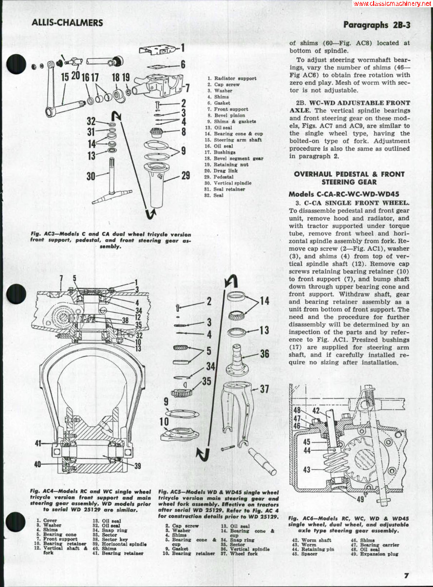
Paragraphs 1-2A ALLIS-CHALMERS FRONT SYSTEM-TRICYCLE AND AXLE TYPES ADJUSTMENT OF PEDESTAL AND FRONT STEERING GEAR Models C-CA-RC-WC-WD-WD45 1. C-CA SINGLE FRONT WHEEL. To adjust vertical spindle bearings, vary the shims (4—Fig. ACl), lo- cated between top of shaft and bearing cone. Radiator must be removed to obtain access to shims. Backlash between bevel gears of front (auxiliary) steering unit should be .002, and is adjusted by varying the shims (9) after removing the radiator. Alternate the shims with gaskets to prevent oil leaks. lA. C-CA ADJUSTABLE FRONT AXLE. The front support unit on these models houses the front steering gear and carries the pivot pin for the front axle. Internal construction, Fig. AC2, is same as single wheel models. To ad- just, follow same procedure as out- lined for single wheel C and CA in preceding paragraph. IB. C-CA DUAL FRONT WHEELS. To adjust vertical spindle bearings, vary the shims (4—Fig. AC3) under cap screw (2) at top of shaft. To gain access to shims, remove the pedestal unit from the front support. Backlash between bevel gears of front (auxiliary) steering gear should be .002. Adjust by varying the shims (9) being sure to alternate shims with gaskets to prevent oil leaks. 2. RC-WC-WD-WD45 SINGLE FRONT WHEEL. On RC-WC, and WD models prior serial WD25129, the wheel fork and vertical spindle are integral as shown in Fig. AC4. On later WD, after serial WD25128, and WD45, the wheel fork is flange bolted to the vertical spindle as shown in Fig. ACS. Adjust vertical spindle bearings by varying shims (4) located at top of shaft underneath the bearing cone re- tainer. To adjust steering wormshaft bear- ings, vary shims (46—Fig. AC6) to ob- tain free rotation with zero end play. Mesh of worm with sector is not ad- justable. Front wheel bearings are adjusted by varying the number of shims (40— Fig. AC4) located between the bearing retainer and wheel hub. 2A. RC-WC-WD WD45 D U A L FRONT WHEELS. To adjust the ver- tical spindle shaft bearings to the de- sired .001-.003 end play, vary number tr—2 20 Fig. ACI-Mocfefs C and CA singl9 wheel tric/cfe ver- sion front support and front steering gear assem- bly. 1. Radiator support 2. Cap screw a. Washer 4. Shims 5. Bearing: cone & cup 6. Gasket 7. Front support 8. Bevel pinion 9. Shims & gaskets 10. Bearing; retainer 12. Vertical shaft & fork 13. Oil seal 14. Bearing cup & eon« 16. Steering arm shaft 16. Oil seal 17. Bushinsrs 18. Bevel segment gear 19. Retaining nut 20. Drag link Fig. ACa-Modefs C and CA adfustoble axle version front support, front steof' ing gear, and axlo assent' bly. 1. Radiator support 2. Cap screw 3. Washer 4. Shims 6. Bearing cone A cup 6. Gasket 7. Front support 8. Bevel pinion 9. Gasket 10. Bearing retainer 13. Oil seal 14. Bearing cone & cup 16. Steering arm shaft 16. Oil seal 17. Bushings 18. Bevel segment gear 19. Retaining nut 20. Drag link 21. Vertical spindle & center steering arm 22. Pivot bracket 23. Axle main member 24. Spindle support 26. Bushings 26. Steering spindle 27. Bushing (radius rod^ 27
ALLIS-CHALMERS Paragraphs 2B-3 1. Radiator support 2. Cap screw 3. Washer 4. Shims 6. Gasket 7. Front support 8. Bevel pinion 9. Shims & gaskets 13. Oil seal 14. Bearing cone & cup 16. Steering arm shaft 16. Oil seal 17. Bushings 18. Bevel segment 19. Retaining nut 20. Drag link 29. Pedestal 30. Vertical spindle 31. Seal retainer 32. Seal Fig. AC3—Mode/s C and CA dual wheel trieyclo version front support, pedestal, and front steering gear as^ sembly. 14 40 Fig. AC4-Models RC and WC single wheel tricycle version front support and main steering gear assembly, WD models prior to serial WD 25129 are similar. 1. Cover 3. Washer 4. Shims 6. Bearing cone 7. Front support 10. Bearing retainer 12. Vertical shaft & fork 13. Oil sea] 32. Oil seal 34. Snap ring 36. Sector 38. Sector key 39. Horizontal spindle 40. Shims 41. Bearing retainer Fig. ACS-Models WD & WD4S single wheel tricycle version main steering gear and wheel fork assembly. Effective on tractors after serial WD 25129. kefer to Fig, AC 4 for construction details prior to WD 25T29. 2. Cap screw 8. Washer 4. Shims 6. Bearing cone & cup 9. Gasket 10. Bearing retains cone & 18. Oil seal 14. Bearing cup 34. Snap ring 36. Sector 36. Vertical spindle 87. Wheel fork of shims (60—Fig. AC8) located at bottom of spindle. To adjust steering wormshaft bear- ings, vary the number of shims (46— Fig AC6) to obtain free rotation with zero end play. Mesh of worm with sec- tor is not adjustable. 2B. WC-WD ADJUSTABLE FRONT AXLE. The vertical spindle bearings and front steering gear on these mod- els. Figs. AC7 and AC9, are similar to the single wheel type, having the bolted-on type of fork. Adjustment procedure is also the same as outlined in paragraph 2. OVERHAUL PEDESTAL & FRONT STEERING GEAR Models C-CA-RC-WC-WD-WD45 3. C-CA SINGLE FRONT WHEEL. To disassemble pedestal and front gear unit, remove hood and radiator, and with tractor supported under torque tube, remove front wheel and hori- zontal spindle assembly from fork. Re- move cap screw (2—Fig. ACl), washer (3), and shims (4) from top of ver- tical spindle shaft (12). Remove cap screws retaining bearing retainer (10) to front support (7), and bump shaft down through upper bearing cone and front support. Withdraw shaft, gear and bearing retainer assembly as a unit from bottom of front support. The need and the procedure for further disassembly will be determined by an inspection of the parts and by refer- ence to Fig. ACl. Presized bushings (17) are supplied for steering arm shaft, and if carefully installed re- quire no sizing after installation. Fig. AC6-Modefs RC, WC, WD & WD45 single wheel, dual wheel, and adjustable axle type steering gear assembly. 42. Worm shaft 48. Worm 44. Retaining pin 46. Spacer 46. Shims 47. Bearing carrier 48. Oil seal 49. Expansion plug
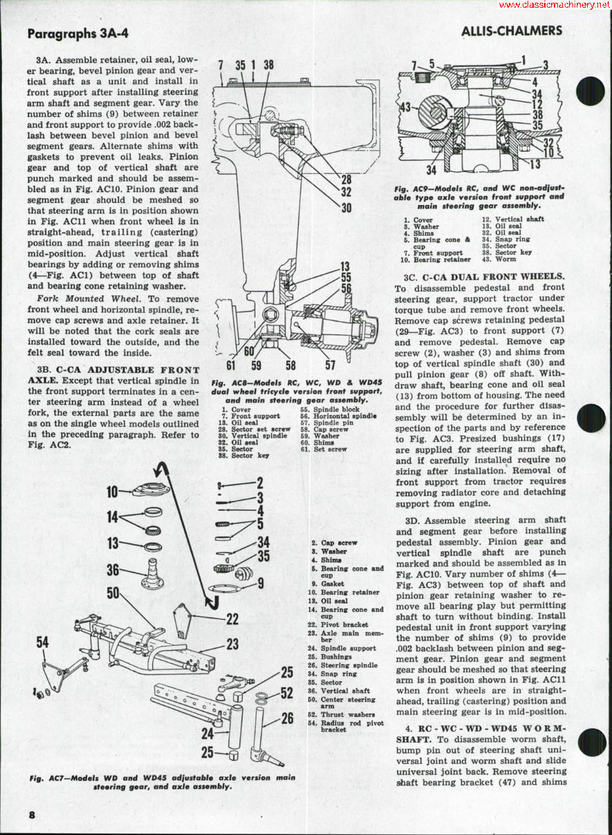
Paragraphs 3A-4 ALLiS-CHALMERS 3A. Assemble retainer, oil seal, low- er bearing, bevel pinion gear and ver- tical shaft as a unit and install in front support after installing steering arm shaft and segment gear. Vary the number of shims (9) between retainer and front support to provide .002 back- lash between bevel pinion and bevel segment gears. Alternate shims with gaskets to prevent oil leaks. Pinion gear and top of vertical shaft are punch marked and should be assem- bled as in Fig. ACIO. Pinion gear and segment gear should be meshed so that steering arm is in position shown in Fig. AC 11 when front wheel is in straight-ahead, trailing (castering) position and main steering gear is in mid-position. Adjust vertical shaft bearings by adding or removing shims (4—Fig. ACl) between top of shaft and bearing cone retaining washer. Fork Mounted Wheel. To remove front wheel and horizontal spindle, re- move cap screws and axle retainer. It will be noted that the cork seals are installed toward the outside, and the felt seal toward the inside. 3B. C-CA ADJUSTABLE FRONT AXLE. Except that vertical spindle in the front support terminates in a cen- ter steering arm instead of a wheel fork, the external parts are the same as on the single wheel models outlined in the preceding paragraph. Refer to Fig. AC2. 7 35 1 38 .\ I / 61 59 58 Fig, ACB-Models kC, WC, WD & WD45 dual wheel tricycle version front support, and main steering gear assembly, 66. Spindle block 66. Horizontal spindl* 67. Spindle pin 68. Cap screw 69. Washer 60. Shims 61. Set screw 1. Cover 7. Front support 13. Oil seal 28. Sector set screw 30. Vertical spindle 82. Oil seal 85. Sector 88. Sector key 54 2. 8. 4. 6. 9. 10. 18. 14. 22. 28. 24. 26. 26. 34. 86. 36. 60. 62. 64. Cap screw Washer Shims Bearing cone and cup Gasket Bearing retainer Oil seal Bearing cone and cup Pivot bracket Axle main mem- ber Spindle support Bushings Steering spindle Snap ring Sector Vertical shaft Center steering arm Thrust washers Radius rod pivot bracket Fig, AC9-Models RC, and WC non-adjust- able type axle version front support and main steering gear assembly. 1. Cover 8. Washer 4. Shims 6. Bearing cone & cup 7. Front support 10. Bearing retainer 12. Vertical shaft 13. Oil seal 32. Oil seal 34. Snap ring 36. Sector 38. Sector key 43. Worm Fig. ACJ-Models WD and WD45 adjustable axle version main steering gear, and axle assembly. 3C. C-CA DUAL FRONT WHEELS. To disassemble pedestal and front steering gear, support tractor under torque tube and remove front wheels. Remove cap screws retaining pedestal (29—Fig. AC3) to front support (7) and remove pedestal. Remove cap screw (2), washer (3) and shims from top of vertical spindle shaft (30) and pull pinion gear (8) off shaft. With- draw shaft, bearing cone and oil seal (13) from bottom of housing. The need and the procedure for further disas- sembly will be determined by an in- spection of the parts and by reference to Fig. AC3. Presized bushings (17) are supplied for steering arm shaft, and if carefully installed require no sizing after installation. Removal of front support from tractor requires removing radiator core and detaching support from engine. 3D. Assemble steering arm shaft and segment gear before installing pedestal assembly. Pinion gear and vertical spindle shaft are punch marked and should be assembled as in Fig. ACIO. Vary number of shims (4— Fig. AC3) between top of shaft and pinion gear retaining washer to re- move all bearing play but permitting shaft to turn without binding. Install pedestal unit in front support varying the number of shims (9) to provide .002 backlash between pinion and seg- ment gear. Pinion gear and segment gear should be meshed so that steering arm is in position shown in Fig. ACll when front wheels are in straight- ahead, trailing (castering) position and main steering gear is in mid-position. 4. RC - WC " WD - WD45 W O R M- SHAFT. To disassemble worm shaft, bump pin out of steering shaft uni- versal joint and worm shaft and slide universal joint back. Remove steering shaft bearing bracket (47) and shims
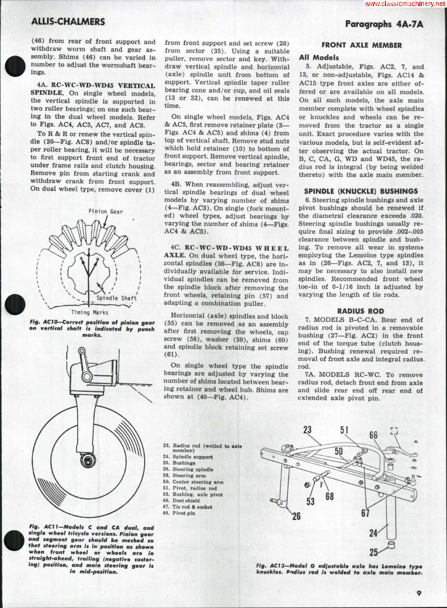
ALLIS-CHALMERS (46) from rear of front support and withdraw worm shaft and gear as- sembly. Shims (46) can be varied in number to adjust the wormshaft bear- ings. 4A. RC-WC-WD-WD45 VERTICAL SPINDLE. On single wheel models, the vertical spindle is supported in two roller bearings; on one such bear- ing in the dual wheel models. Refer to Figs. AC4, ACS, AC7, and AC8. To R & R or renew the vertical spin- dle (30—Fig. AC8) and/or spindle ta- per roller bearing, it will be necessary to first support front end of tractor under frame rails and clutch housing. Remove pin from starting crank and withdraw crank from front support. On dual wheel type, remove cover (1) Pinion Gear Timing Marks Fig. ACIO—Correct position of pinion gear on vertical shaft is indicated by punch marks. Fig, ACll-Models C and CA dual, and single wheel tricycle versions. Pinion gear and segment gear should be meshed so that steering arm is in position as shown when front wheel or wheels are in straight-ahead, trailing (negative caster^ ing) position, and main steering gear is in mid-position. from front support and set screw (28) from sector (35). Using a suitable puller, remove sector and key. With- draw vertical spindle and horizontal (axle) spindle unit from bottom of support. Vertical spindle taper roller bearing cone and/or cup, and oil seals (13 or 32), can be renewed at this time. On single wheel models. Figs. AC4 & AC5, first remove retainer plate (3— Figs, AC4 & ACS) and shims (4) from top of vertical shaft. Remove stud nuts which hold retainer (10) to bottom of front support. Remove vertical spindle, bearings, sector and bearing retainer as an assembly from front support. 4B. When reassembling, adjust ver- tical spindle bearings of dual wheel models by varying number of shims (4—Fig. AC3). On single (fork mount- ed) wheel types, adjust bearings by varying the number of shims (4—Figs. AC4 & ACS). 4C. RC-WC-WD-WD45 W H E E L AXLE. On dual wheel type, the hori- zontal spindles (S6—Fig. AC8) are in- dividually available for service. Indi- vidual spindles can be removed from the spindle block after removing the front wheels, retaining pin (S7) and adapting a combination puller. Horizontal (axle) spindles and block (S5) can be removed as an assembly after first removing the wheels, cap screw (58), washer (59), shims (60) and spindle block retaining set screw (61). On single wheel type the spindle bearings are adjusted by varying the number of shims located between bear- ing retainer and wheel hub. Shims are shown at (40—^Fig. AC4). Paragraphs 4A-7A FRONT AXLE MEMBER All Models 5. Adjustable, Figs. AC2, 7, and 13, or non-adjustable. Figs. AC14 & AC 15 type front axles are either of- fered or are available on all models. On all such models, the axle main member complete with wheel spindles or knuckles and wheels can be re- moved from the tractor as a single unit. Exact procedure varies with the various models, but is self-evident af- ter observing the actual tractor. On B, C, CA, G, WD and WD45, the ra- dius rod is integral (by being welded thereto) with the axle main member. SPINDLE (KNUCKLE) BUSHINGS 6. Steering spindle bushings and axle pivot bushings should be renewed if the diametral clearance exceeds .020. Steering spindle bushings usually re- quire final sizing to provide .002-.005 clearance between spindle and bush- ing. To remove all wear in systems employing the Lemoine type spindles as in (26—Figs. AC2, 7, and 13), it may be necessary to also install new spindles. Recommended front wheel toe-in of 0-1/16 inch is adjusted by varying the length of tie rods. RADIUS ROD 7. MODELS B-C-CA. Rear end of radius rod is pivoted in a removable bushing (27—Fig. AC2) in the front end of the torque tube (clutch hous- ing). Bushing renewal required re- moval of front axle and integral radius, rod. 7A. MODELS RC-WC. To remove radius rod, detach front end from axle and slide rear end off rear end of extended axle pivot pin. 51 23. Radius rod (welded to asde member) 24. Spindle support 25. Bushings 26. Steering spindle 33. Steering arm 60. Center steering arm 61. Pivot, radius rod 63. Bushing, axle pivot 66. Dust shield 67. Tie rod & socket 68. Pivot pin Fig. AC 13—Model G adjustable axle has Lemoine type knuckles, Pndius rod is welded to axle main member.
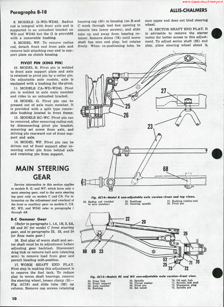
Paragraphs 8-18 8. MODELS G-WD-WD4S. Radius rod is integral with front axle and is supported in an unbushed bracket on WD and WD45 but the G is provid4'd with a removable bushing. 9. MODEL WF. To remove radius rod, detach front end from axle and remove bolt attaching rear end to sup- port plate on clutch housing. PIVOT PIN (KING PIN) 10. MODEL B. Pivot pin is welded to front axle support plate and axle is retained to pivot pin by a cotter pin. On adjustable axle models, axle is equipped with a bushing for the pivot. 11. MODELS CA-WD-WD4S. Pivot pin is welded to axle main member and rides in an unbushed bracket. 12. MODEL G. Pivot pin can be pressed out of axle main member. It is provided with a split type renew- able bushing located in front frame. 13. MODELS RC-WC. Pivot pin can be removed, after removing radius rod, by disconnecting pivot pin bracket, removing set screw from axle, and driving pin rearward out of front sup- port and axle. 14. MODEL WF. Pivot pin can be driven out of front support after re- moving cotter pin from behind axle and retaining pin from support. MAIN STEERING GEAR Service information in this section applies to models B, G, and WF, which have only a main steering gear, and to the main steering ing gear only on models C and CA, For in- formation on the adjustment and overhaul oi the front or auxiliary gear on models C, CA, RC, WD, and WD45 refer to paragraphs 1 through 4A. B-C Gemmer Gear (Refer to paragraphs 1, lA, IB, 3, 3A, 3B and 3C for model C front steering gear, and to paragraphs 22, 23, and 24 for Ross main gear.) 16. End play of worm shaft and sec- tor shaft must be in adjustment before adjusting gear backlash. Disconnect drag link or remove ball arm (steering arm) to remove load from gear and permit locating mid-position. 17. WORM SHAFT END PLAY. First step in making this adjustment is to remove the fuel tank. To reduce play in worm shaft bearings, remove the steering wheel, loosen clamp (81— Fig. AC16) and slide tube (82) up column. Remove cap screws retaining housing cap (80) to housing (on B and C work through tool box opening to remove two lower screws), and slide tube up and away from bearing re- tainer. Remove shims (78) until worm shaft has zero end play, but rotates freely. When re-positioning tube, be ALLIS-CHALMERS sure upper end does not bind steering wheel. 18. SECTOR SHAFT END PLAY. It is advisable to remove the starter motor for better access to this adjust- ment. To adjust sector shaft (8S) end play, place steering wheel about % Fig. AC 14—Model B non-ad/u stable axle version—front and top views. 23. Radius rod (welded to axle member) 26. Bushings 26. Steering spindle 27. Bushing (radius rod) 68. Pivot pin 26 72 Fig. ACI5~Models ftC and WC non-adjustable axle version-front view. 20. Drag link 22. Front support 23. Axle member 26. Bushing 26. Spindle 62. Thrust washer 68. Pivot jpin 69. Set screw 70. Oil seal, hub 71. Spindle lock stud 72. Expansion plag 73. Spindle pia 10
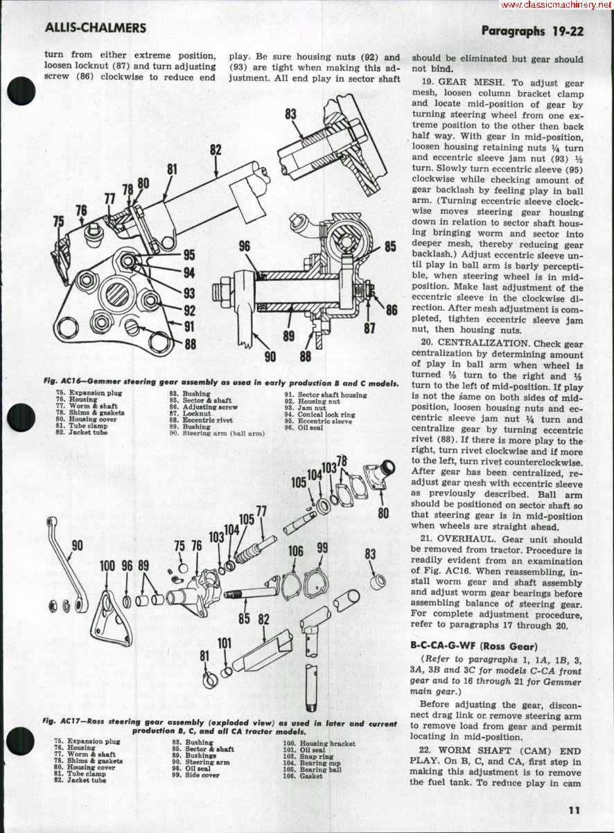
ALLIS-CHALMERS Paragraphs 19-22 turn from either extreme position, loosen locknut (87) and turn adjusting screw (86) clockwise to reduce end play. Be sure housing nuts (92) and (93) are tight when making this ad- justment. All end play in sector shaft 75 87 90 88 Fig. ACI6--aeminer steering gear assembly as vsetf in early production B and C models. 75. Expansion plug 76. Housing 77. Worm £ shaft 78. Shims & gaskets 80. Housing cover 81. Tube clamp 82. Jacket tube 83. Bushing 86. Sector A shaft 86. Ad justing screw 87. Locknut 88. Eccentric rivet 89. Bushing 90. Steering arm (ball arm) 91. Sector shaft housing 92. Housing nut 93. Jam nut 94. Conical lock ring 96. Eccentric sleeve 96. Oil seal 90 75 76 100 96 89 ,^ Hg, ACir—koss steering gear assembly (exploded view) as used in later and current production B, C, and all CA tractor models. 76. Expansion plug 76. Housing 77. Worm A shaft 78. Shims ft gaslcets 80. Housing cover 81. Tube clamp 82. Jacket tube 83. Bushing 86. Sector & shaft 89. Bushings 90. Steering arm 96. Oil seal 99. Side cover 100. Housing bracket 101. Oil seal 103. Snap ring 104. Bearing cup 106. Bearing ball 106. Gasket should be eliminated but gear should not bind. 19. GEAR MESH. To adjust gear mesh, loosen column bracket clamp and locate mid-position of gear by turning steering wheel from one ex- treme position to the other then back half way. With gear in mid-position, loosen housing retaining nuts V4, turn and eccentric sleeve jam nut (93) V2 turn. Slowly turn eccentric sleeve (9S) clockwise while checking amount of gear backlash by feeling play in ball arm. (Turning eccentric sleeve clock- wise moves steering gear housing down in relation to sector shaft hous- ing bringing worm and sector into deeper mesh, thereby reducing gear backlash.) Adjust eccentric sleeve un- til play in ball arm is barly percepti- ble, when steering wheel is in mid- position. Make last adjustment of the eccentric sleeve in the clockwise di- rection. After mesh adjustment is com- pleted, tighten eccentric sleeve jam nut, then housing nuts. 20. CENTRALIZATION. Check gear centralization by determining amount of play in ball arm when wheel is turned % turn to the right and % turn to the left of mid-position. If play is not the same on both sides of mid- position, loosen housing nuts and ec- centric sleeve jam nut V4 turn and centralize gear by turning eccentric rivet (88). If there is more play to the right, turn rivet clockwise and if more to the left, turn rivet counterclockwise. After gear has been centralized, re- adjust gear ijiesh with eccentric sleeve as previously described. Ball arm should be positioned on sector shaft so that steering gear is in mid-position when wheels are straight ahead. 21. OVERHAUL. Gear unit should be removed from tractor. Procedure is readily evident from an examination of Fig. AC16. When reassembling, in- stall worm gear and shaft assembly and adjust worm gear bearings before assembling balance of steering gear. For complete adjustment procedure, refer to paragraphs 17 through 20. B-C-CA-G-WF (Ross Gear) (Refer to paragraphs 1, lA, IB, 3, 3A, 3B and 3C for models C-CA front gear and to 16 through 21 for Gemmer main gear.) Before adjusting the gear, discon- nect drag link or remove steering arm to remove load from gear and permit locating in mid-position. 22. WORM SHAFT (CAM) END PLAY. On B, C, and CA, first step in making this adjustment is to remove the fuel tank. To reduce play in cam 11
This is a comprehensive service repair manual for the Allis Chalmers Model B Tractor. It contains detailed illustrations, diagrams, wiring schematics, and specifications, along with step-by-step instructions. The manual is printable, allowing you to take the necessary pages with you into the garage or workshop. It is an invaluable source of repair and service information for both DIY enthusiasts and experienced mechanics.
The manual covers various systems including the engine, electrical, emission control, fuel, suspension, clutch, transaxle, driveshaft, axle, steering, brake, body interior and exterior, body electrical, and restraint systems.
Product Details:
File Format: PDF
Language: English
Specifications: Fully Printable, Zoom IN/OUT
Delivery: Instant Download
Requirements: Adobe Reader & Win
Compatible: All Versions of Windows & Mac
The manual includes detailed substeps, notes, cautions, warnings, numbered instructions, and bold figure numbers to facilitate easy understanding. It also provides troubleshooting and electrical service procedures combined with detailed wiring diagrams for ease of use.
Keywords:
General Information
Engine Mechanical System
Engine Electrical System
Emission Control System
Fuel System
Suspension System
Clutch System
Manual Transaxle System
Automatic Transaxle System
Driveshaft and Axle
Steering System
Brake System
Body Interior and Exterior
Body Electrical System
Restraint
Plus more!
Recently Viewed
5,521,897Happy Clients
2,594,462eManuals
1,120,453Trusted Sellers
15Years in Business
Price:
Actual Price:
Allis Chalmers Model B Tractor Workshop Service Repair