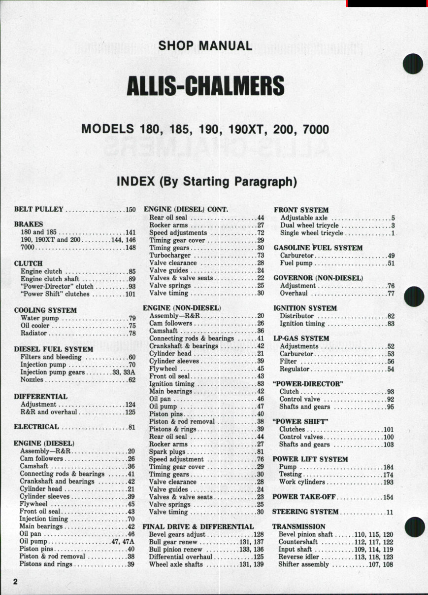
SHOP MANUAL AUIS-CHALMERS MODELS 180, 185, 190, 190XT, 200, 7000 INDEX (By Starting Paragraph) BELT PULLEY 150 ENGINE (DIESEL) CONT. BRAKES 180 and 185 141 190, 190XT and 200 144, 146 7000 148 CLUTCH Engine clutch 85 Engine clutch shaft 89 "Power-Director" clutch 93 "Power Shift" dutches 101 COOLING SYSTEM Water pump ,,. 79 Oil cooler 75 Radiator .78 DIESEL FUEL SYSTEM Filters and bleeding 60 Injection pump 70 Injection pump gears 33, 33A Nozzles 62 DIFFERENTIAL Adjustment 124 R&R and overhaul 125 ELECTRICAL 81 ENGINE (DIESEL) Assembly—R&R 20 Cam followers 26 Camshaft 36 Connecting rods & bearings 41 Crankshaft and bearings 42 Cylinder head 21 Cylinder sleeves 39 Flywheel ..... 45 Front oil seal 43 Injection timing 70 Main bearings 42 Oil pan 46 Oil pump 47, 47A Piston pins 40 Piston & rod removal 38 Pistons and rings 39 Rear oil seal 44 Rocker arms 27 Speed adjustments 72 Timing gear cover 29 Timing gears 30 Turbocharger 73 Valve clearance 28 Valve guides 24 Valves & valve seats 22 Valve springs 25 Valve timing 30 ENGINE (NON DIESEL) Assembly—R&R., 20 Cam followers 26 Camshaft 36 Connecting rods & bearings 41 Crankshaft & bearings 42 Cylinder head ., 21 Cylinder sleeves 39 Flywheel 45 Front oil seal 43 Ignition timing 83 Main bearings 42 Oil pan 46 Oil pump .47 Piston pins 40 Piston & rod removal 38 Pistons & rings 39 Rear oil seal 44 Rocker arms 27 Spark plugs 81 Speed adjustment 76 Timing gear cover 29 Timing gears 30 Valve clearance 28 Valve guides 24 Valves & valve seats 23 Valve springs 25 Valve timing 30 FINAL DRIVE & DIFFERENTL^L Bevel gears adjust 128 Bull gear renew 131, 137 Bull pinion renew 133, 136 Differential overhaul 125 Wheel axle shafts 131, 139 FRONT SYSTEM Adjustable axle 5 Dual wheel tricycle 3 Single wheel tricycle 1 GASOLINE tUEL SYSTEM Carburetor 49 Fuel pump 51 GOVERNOR (NON DIESEL) Adjustment 76 Overhaul 77 IGNITION SYSTEM Distributor 82 Ignition timing 83 LP GAS SYSTEM Adjustments 52 Carburetor 53 Filter 56 Regulator 54 "POWER DIRECTOR'' Clutch 93 Control valve .92 Shafts and gears 95 "POWER SHIFT" Clutches 101 Control valves 100 Shafts and gears 103 POWER LIFT SYSTEM Pump 184 Testing 174 Work cylinders 193 POWER TAKE-OFF 154 STEERING SYSTEM 11 TRANSMISSION Bevel pinion shaft 110, 115, 120 Countershaft 112. 117, 122 Input shaft 109, 114, 119 Reverse idler 113, 118, 123 Shifter assembly 107, 108
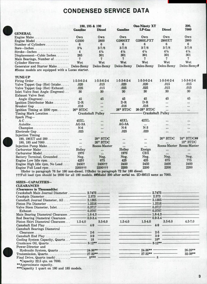
CONDENSED SERVICE DATA 180, 185 & 190 One-Ninety XT GasoUne Diesel Gasoline LP-Gas Diesel GENERAL Engine Make Own Own Own Own Own Engine Model G2500 2800 G2800XT G2800LPXT 2900XT Number of Cylinders 6 6 6 6 6 Bore-Inches 3% 3-7/8 3-7/8 3-7/8 3-7/8 Stroke-Inches 4 47* 4V4 4V4 4V4 Displacement-Cubiclnches 265 801 301 301 301 Main Bearings, Number of 7 7 7 7 7 Cylinder Sleeves Wet Wet Wet Wet Wet Generator and Starter Make Delco-Remy Delco-Remy Delco Remy Delco-Remy Delco-Remy #Some models are equipped with a Lucas starter. TUNE-UP Firing Order 1-5 3-6-2 4 1-5-3-6-2-4 1-5-3-6-2-4 1-5-3-6-2-4 1-5-3-6-2-4 Valve Tappet Gap (Hot) Intake 020 .015 .020 .020 .015 Valve Tappet Gap (Hot) Exhaust ... . 025 .015 .025 .025 .015 Inlet Valve Seat Angle (Degrees)... 30 80 80 30 80 Exhaust Valve Seat Angle (Degrees) 45 45 45 45 45 Ignition Distributor Make D-R ... D-R D-R Breaker Gap 016 ».. .016 .016 Ignition Timing at 2200 rpm 26** BTDC ... 26° BTDC 26-28*» BTDC Timing Mark Location Crankshaft Pulley Crankshaft Pulley Spark Plug— AC 45XL ... 45XL 42XL Autolite AG-3A ... AG-3A Champion N-6 ...• N-6 N-3 Electrode Gap 025 ... . 025 .020 Injection Timing 190, 190XT and 200 ... 28*^ BTDC ... ... 26° BTDC 180, 185 and 7000 26° BTDC Injection Pump Make ... Roosa-Master ... ... Roosa-Master Carburetor Make HoUey ... Holley Ensign Carburetor Model 1970 ... 1970 CBX Battery Terminal, Grounded Neg. Neg. Neg. Neg. Neg. Engine Low Idle rpm 425t 675 425 425 675 Engine High Idle rpm, No Load .... 2450t 2400tt 2450 2450 2400 Engine Full Load rpm 2200ttt 2200ttt 2200 2200 2200 tRefer to paragraph 76 for 180 non-diesel. JtRefer to paragraph 72 for 180 diesel. tttFull load rpm should be 2000 for all 180 models. ##Model 200 after serial no. 2D-69515 same as 7000. SIZES-CAPACITIES- CLEARANCES (Clearances in Thousandths) Crankshaft Main Journal Diameter . 2.7475 2.7475 Crankpin Diameter 2.373 2.373 Camshaft Journal Diameter, All .... 2.1305 2.1305 Piston Pin Diameter 1.2516 1.2516 Valve Stem Diameter, Inlet 0.3717 0.3717 Exhaust 0.3707 0.3707 Main Bearing Diametral Clearance.. 1.6-4.3 1.6-4.3 Rod Bearing Diametral Clearance... 0.9-3.4 0.9-3.4 Piston Skirt Diametral Clearance... 1.5-4.0 3.5-6.0 1.5-4.0 1.5-4.0 3.5-6.0 Camshaft End Play 4-9 4-9 Camshaft Bearings Diametral Clearance 2-6 2-5 Camshaft End Play 3-9 3-9 Cooling System Capacity, Quarts ... 18 18* Crankcase Oil, Quarts 8-12** 8-12** Power-Director and Hydraulic System, Quarts 24-36** 24-36** Transmission, Quarts 27-32** • 27-32** Final Drive, Quarts (each) 8*** 8 *Capacity 22.5 qts. on 7000. **Approximate capacity. ***Capacity 1 quart on 180 and 185 models. 200, 7000 Own 2900 6 3-7/8 4V4 301 7 Wet Delco-Remy # 1-5-3-6-2-4 .015 .015 30 45 24° BTDC## 18° BTDC Roosa Master Neg. 775 2400 2200 4.5-7.0 26-28** 32-38**
Paragraphs 1-3 ALLIS-CHALMERS CONDENSED SERVICE DATA CONT. TIGHTENING TORQUES- FOOT-POUNDS General Recommendations .... Connecting Rod Screws Cylinder Head Screws Flywheel Screws Injection Nozzel Nuts Main Bearing Screws . —40-45- —150 _68-73— 9-12 -130-140- See End of Shop Manual —40-45- —150— --68-73— 9-12 11-13 -130-140- FRONT SYSTEM SINGLE WHEEL TRICYCLE 1. WHEEL ASSEMBLY. The single front wheel assembly may be removed after raising front of tractor and re- moving bolt (3—Fig. 1) at each end of wheel axle (1). To renew bearings and/or seals, first remove wheel assembly; then unbolt and remove bearing retainer (10—Fig. 2), seal (4), seal retainer (5) and shims (9). Drive or press on opposite end to remove axle (8), bearing cones (7) and bearing cup from retainer side of hub. Drive the remaining seal and bearing cup out of hub. Remove bearing cones from spindle. Soak new felt seals in oil prior to installing seals and seal retainers. Drive bearing cup into hub until cup is firmly seated. Drive bearing cones tightly against shoulders on axle. Pack bearings with No. 2 wheel bearing grease. Install axle and bearing cup in against cone. When installing bearing retainer, vary number of shims (9—Fig. 2) to give bearings a free rolling fit with no end play. Front wheel bearings should be repacked with No. 2 wheel bearing grease after each 500 hours of use. If necessary to renew wheel hub or repair tire, deflate tire before unbolting Fig. t~'Explod9<l vf9W of th0 single front fork and associatBd parts. Fig. 2^Exf>lod9d fiaw of singla front wheel assembly. 1. Side rings (2) 2. Tire 3. Wheel hub 4. Seals (2) 5. Seal reUiners (2) and removing tire retaining rings (1-Fig. 2). 2. R&R SINGLE WHEEL FORK. Raise front end of tractor, remove bolts (3—Fig. 1) from each end of wheel axle and remove wheel assembly from fork. Unbolt and remove fork (2) from steering gear shaft. Make sure that steering gear is cen- tered and reinstall fork with caster to rear. Tighten retaining screws to a torque of 180-190 ft.-lbs. Fig. 3—Dual wheel tricycle spindles (2) can be removed after removing groove pins {$). 1. Axle 2. Fork 3. BolU {2) 1. Pedestal 2. Spindle 3. Shield 6. Bearings cups (2) 7. Bearing cones (2) 8. Axle 9. Shims 10. Bearing retainer DUAL WHEEL TRICYCLE 3. WHEEL ASSEMBLY. The stamped steel wheel disc is reversible on hub. Bearing adjustment is made by tightening retaining nut on spindle until bearings are firmly seated, back- ing nut off one castellation and in- stalling cotter pin. Bearings should be repacked with No. 2 wheel bearing grease after each 500 hours of use. Dual wheel pedestal spindles are equipped with an external lip type seal (1—Fig. 4). The three lips on outside diameter of seal contact a steel wear sleeve that is pressed into the front wheel hub. Drive wear sleeve into hub with crimped edge of wear sleeve Fig. 4—Expioded view of wheel hub and bearing used on dual wheel tricycle and wide front axle modeis. 4. Beaiing spacer 5. Groove pin 1. Wear sleeve and seal 2. Inner bearing 3. Wheel hub 4. Outer bearing 5. Washer 6. Nut 7. Hub cap
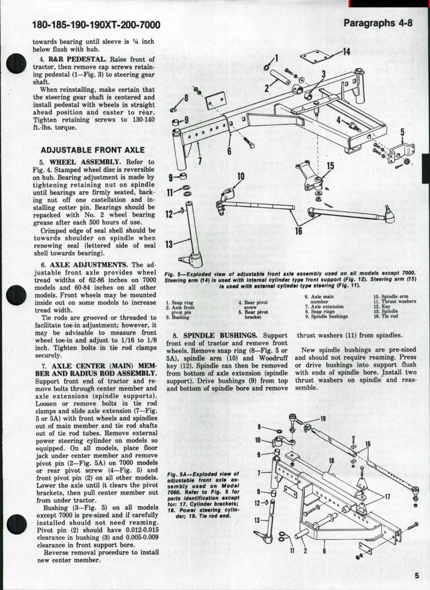
180-185-190-190XT.200.7000 Paragraphs 4-8 towards bearing until sleeve is V4 inch below flush with hub. 4. R&R PEDESTAL. Raise front of tractor, then remove cap screws retain- ing pedestal (1—Fig. 3) to steering gear shaft. When reinstalling, make certain that the steering gear shaft is centered and install pedestal with wheels in straight ahead position and caster to rear. Tighten retaining screws to 130-140 ft.-lbs. torque. ADJUSTABLE FRONT AXLE 5. WHEEL ASSEMBLY. Refer to Fig. 4. Stamped wheel disc is reversible on hub. Bearing adjustment is made by tightening retaining nut on spindle until bearings are firmly seated, back- ing nut off one castellation and in- stalling cotter pin. Bearings should be repacked with No. 2 wheel bearing grease after each 500 hours of use. Crimped edge of seal shell should be towards shoulder on spindle when renewing seal (lettered side of seal shell towards bearing). 6. AXLE ADJUSTMENTS. The ad- justable front axle provides wheel tread widths of 62-86 inches on 7000 models and 60-84 inches on all other models. Front wheels may be mounted inside out on some models to increase tread width. Tie rods are grooved or threaded to facilitate toe-in adjustment; however, it may be advisable to measure front wheel toe-in and adjust to 1/16 to 1/8 inch. Tighten bolts in tie rod clamps securely. 7. AXLE CENTER (MAIN) MEM- BER AND RADIUS ROD ASSEMBLY. Support front end of tractor and re- move bolts through center member and axle extensions (spindle supports). Loosen or remove bolts in tie rod clamps and slide axle extension (7—Fig. 5 or 5A) with front wheels and spindles out of main member and tie rod shafts out of tie rod tubes. Remove external power steering cylinder on models so equipped. On all models, place floor jack under center member and remove pivot pin (2—Fig. 5A) on 7000 models or rear pivot screw (4—Fig. 5) and front pivot pin (2) on all other models. Lower the axle until it clears the pivot brackets, then pull center member out from under tractor. Bushing (3—Fig. 5) on all models except 7000 is pre-sized and if carefully installed should not need reaming. Pivot pin (2) should have 0.012-0.015 clearance in bushing (3) and 0.005-0.009 clearance in front support bore. Reverse removal procedure to install new center member. Fig, 5—Exploded view of adiustabh front axle assembly used on all models except 7000: Steering arm 04) Is used with internal cylinder type front support (Fig. 12), Steering arm (iS) I9 U99d with external cylinder type steering (Ffg. IT). 1. Snap ring 2. Axle front pivot pin 3. Bushing 4. Rear pivot screw 5. Rear pivot bracket 6. Axle main member 7. Axle extension 8. Snap rings 9. Spindle bushings 10. Spindle arm 11. Thrust washers 12. Key 13. Spindle 16. Tie rod 8. SPINDLE BUSHINGS. Support front end of tractor and remove front wheels. Remove snap ring (8—Fig. 5 or 5A), spindle arm (10) and Woodruff key (12). Spindle can then be removed from bottom of axle extension (spindle support). Drive bushings (9) from top and bottom of spindle bore and remove thrust washers (11) from spindles. New spindle bushings are pre-sized and should not require reaming. Press or drive bushings into support flush with ends of spindle bore. Install two thrust washers on spindle and reas- semble. 16 Fig. SA-^Explod^d view of adiustBbl9 front axle as- sembly used on Model 7000. Refer to Fig. 5 for parts Identification except for: t7. Cylinder brackets; 18. Power steering cylin- der; 19. Ti9 rod 9nd,
Paragraphs 9-13 ALLIS-CHALMERS FRONT SUPPORT Models With External Steering Cylinder 9. REMOVE AND REINSTALL. To remove front support casting from ad- justable front axle models with an external steering cylinder, proceed as follows: Remove hood, grille and hood side panels. Drain cooling system and remove air cleaner and air cleaner tube. Disconnect hoses and remove radiator. Disconnect steering cylinder. Remove radius rod pivot pin. (4—Fig. 5) on all models except 7000 models. Support tractor under torque housing so there is no weight on front wheels. Attach a hoist to front support, remove cap screws attaching front support, to side rails and roll front support and axle away from tractor. NOTE: If front support casting binds between the side rails, loosen the bolts attaching side rails to the engine front support plate. Front support casting can be separated from axle assembly after removing pivot pin. When reinstalling, tighten the radius rod pivot screw (4—Fig. 5) on all models except 7000 models to at least 150 ft.-lbs. Tighten cap screws attach- ing side rails to the engine front support plate to 70-75 ft.-lbs. On tractors prior to Serial No. 190 2807, tighten the eight 5/8-inch screws attaching side rails to front support to 130-140 ft.-ibs torque. On tractors after Serial No. 190-2806, and all model 200 tractors, tighten side rail to front support %-inch cap screws to 310-320 ft.-lbs. torque. Models With intemai (Dual) Steering Cylinders 10. REMOVE AND REINSTALL. The front support casting (5—Fig. 12) on all tricycle models and some adjust- able axle models is used as the steering cylinder. To remove the front support, proceed as follows: Remove hood, grille and hood side panels. Drain cooling system and remove air cleaner and air cleaner tube. Disconnect hoses and remove radiator. Disconnect the steer- ing hydraulic lines from "Tee" fittings on front support. On adjustable front axle models, remove radius rod pivot pin (4—Fig. 5). On all models, support tractor under torque housing So there is no weight on front wheels. Attach a hoist to the front support, remove cap screws attaching front support to side rails and roll the front support and wheels away from tractor. NOTE: If front support casting binds between side rails, loosen boits attach- ing side rails to engine front support piate. When reinstalling, tighten cap screws attaching side rails to engine front support plate to a torque of 70-75 ft.-lbs. On tractors prior to Serial No. 190 2807, tighten the eight (5/8-inch) cap screws attaching side rails to front support to 130-140 ft.-lbs of torque. On tractors after Serial No. 190-2806, and all model 200 tractors, tighten side rail to front support (V4 4nch) cap screws to 310-320 ft.-lbs. torque. On adjustable front axle models, radius rod pivot pin should be tightened to at least 150 ft.-lbs. torque. STEERING SYSTEM All models are equipped with hydro- static steering system that has no mechanical linkage between the steer- ing wheel and front axle. The control valve unit (Fig. 9) contains a rotary metering motor, a commutator feed vaive sleeve and a selector valve spool. In the event of engine or hydraulic power failure, the metering motor becomes a rotary pump to actuate the power steering cylinder when the steer- ing wheei is turned. A checi( vaive in the control valve housing allows re- circuiation of fiuid within the control valve and steering eyiinder during manual operation. Power for the steering system is supplied by a gear type pump that is driven from the engine camshaft gear. The power steering pump aiso supplies hydraulic pressure to "Power-Director" ciutch and hydraulic pto clutch sys- tems. TROUBLE SHOOTING 11. Before attempting to adjust or repair the power steering system, the cause of any malfunction should be lo- cated. Refer to the following para- graphs for possible causes of power steering system malfunction: Irregular or "Sticky" steering. If ir- regular or "sticky" feeling is noted when turning the steering wheel with forward motion of tractor stopped and with engine running at rated speed, or if steering wheel continues to rotate after being turned and released, foreign material in the power steering fluid is the probable cause of trouble. Clean the magnetic oil filter, renew throw- away type oil filter, drain "Power- Director" compartment (hydraulic sump) and refill with clean oil. If trouble is not corrected, the power steering valve assembly should be re- moved and serviced; refer to paragraph 15. Steering Cylinder ''Hesitates**. If steering cylinder appears to pause in travel when steering wheel is being turned steadily, probable cause of trouble is air trapped in the power steering cylinder. Bleed the cylinder as outlined in paragraph 12. Slow Steering. Slow steering may be caused by low oil flow from pump. Check time required for full stroke travel of jwwer steering cylinder; first with tractor on the front wheels, then with front end of tractor supported by a jack. If time between the two checks varies considerably, overhaul the power steering pump as outlined in paragraph 186. Loss of Power. Loss of steering power may be caused by system pressure too low. Check and adjust relief valve setting as outlined in paragraph 13, 13A or 13B. LUBRiCATiON AND BLEEDiNG 12. The "Power-Director" compart- ment of the torque housing is utilized as a reservoir for the hydraulic systems including power steering. Capacity is approximately 28 quarts for 190,190XT, 200 and 7000 models, 24 quarts for 180 and 185 models. Oil level on all models except 7000 should be maintained at mark on filler cap dipstick located to left and forward of gear shift. On 190, 190XT and 200 models, it is necessary to remove rear section of gear shift linkage cover for access to dipstick. Oil level on 7000 models should be main- tained between two sight glass gages on right side of torque housing. Allis-Chalmers "Power Fluid" should be used. The power steering system is usually self-bleeding. With engine running at high idle speed, cycle the system through several full strokes of the cylinder. In some cases, it may be necessary to loosen connections at cylinder to bleed trapped air. TESTS AND ADJUSTMENTS 190 and 190XT Models 13. The "Power-Director" clutch and (on models so equipped) the pto clutch are actuated by pressure from the power steering system. Before check- ing the power steering relief pressure, refer to paragraphs 91 and 155 to check the "Power-Director" and pto pres- sures. A pressure and volume (flow) test of the power steering system will disclose whether the pump or relief valve is malfunctioning. To make such a test, proceed as follows: Remove hood right side panel and disconnect steering system return 6
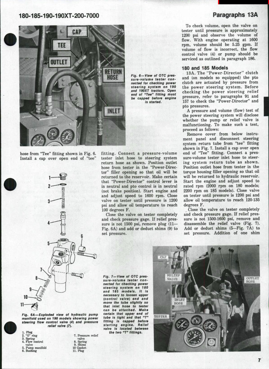
180-185-190-190XT.200-7000 Paragraphs 13A Fig. e—View ot OTC pres- sure-volume tester con- rtected for checking power steering system on 190 and 190XT tractors. Open end of "Tee" fitting must be capped before engine is started. hose from "Tee" fitting shown in Fig. 6. fitting. Connect a pressure-volume Install a cap over open end of "tee" tester inlet hose to steering system return hose as shown. Position outlet hose from tester in the "Power-Direc- tor" filler opening so that oil will be returned to the reservoir. Make certain that "Power-Director" control lever is in neutral and pto control is in neutral (not brake position). Start engine and and adjust speed to 1600 rpm. Close valve on tester until pressure is 1200 psi and allow oil temperature to reach 100 degrees F. Close the valve on tester completely and check pressure gage. If relief pres- sure is not 1500 psi. remove plug (11— Fig. 6A) and add or deduct shims (9) to set pressure. To check volume, open the valve on tester until pressure is approximately 1200 psi and observe the volume of flow. With engine operating at 1600 rpm, volume should be 5.25 gpm. If volume of flow is incorrect, the flow control valve (4) or pump should be serviced as outlined in paragraph 186. 180 and 185 Models 13A. The "Power-Director*' clutch and (on models so equipped) the pto clutch are actuated by pressure from the power steering system. Before checking the power steering relief pressure, refer to paragraphs 91 and 157 to check the "Power-Director" and pto pressures. A pressure and volume (flow) test of the power steering system will disclose whether the pump or relief valve is malfunctioning. To make such a test, proceed as follows: Remove cover from below instru- ment panel and disconnect steering system return tube from "tee" fitting shown in Fig. 7. Install a cap over open end of "Tee" fitting. Connect a pres- sure-volume tester inlet hose to steer- ing system return tube as shown. Position outlet hose from tester in the torque housing filler opening so that oil will be returned to hydraulic reservoir. Start the engine and adjust speed to rated rpm (2000 rpm on 180 models; 2200 rpm on 185 models). Close valve on tester until pressure is 1200 psi and allow oil temperature to reach 120-135 degrees F. Close the valve on tester completely and check pressure gage. If relief pres- sure is not 1500-1600 psi, remove and disassemble the relief valve (Fig. 7). Add or deduct shims (5—Fig. 7A) to set pressure. Addition of one shim Fig. BA—Expioded view of hydraulic pump manifold used on 190 models showing power steering flow control vaive (4) and pressure relief valve (7). 1. Plug 2. "0" ring 3. Spring 4. Flow control valve 5. Pump manifold Q. Bushing 7. Pressure relief valve 8. Spring 9. Shims 10 Gasket 11. Plug Fig. T—Vlew of OTC pres- sure-volume tester con- nected for checking power steering system on 180 and 185 modeis, it is necessary to loosen upper (control vaive) end and move the tube siightiy so that inlet hose to tester can be attached. Make certain that upper end of tube is tight and that "T" fitting is capped before starting engine. Reiief valve is located between the two «T" fittings.
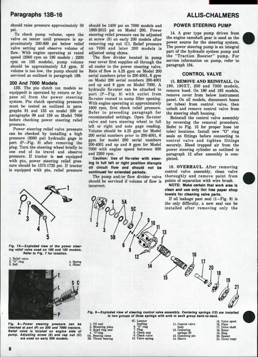
Paragraphs 13B-16 ALLIS-CHALMERS should raise pressure approximately 50 psi. To check pump volume, open the valve on tester until pressure is ap- proximately 200-300 psi below relief valve setting and observe volume of flow. With engine operating at rated speed (2000 rpm on 180 models ; 2200 rpm on 185 models), pump volume should be approximately 5.8 gpm. If volume is too low, the pump should be serviced as outlined in paragraph 189. 200 And 7000 Models 13B. The pto clutch (on models so equipped) is operated by return or by- pass oil from the power steering system. Pto clutch operating pressure must be tested as outlined in para- graphs 91 and 155 on model 200 or paragraphs 99 and 159 on Model 7000 before checking power steering relief pressure. Power steering relief valve pressure can be checked by installing a high pressure (3000 psi) hydraulic gage in port (P—Fig. 8) after removing the plug. Turn the steering wheel briefly to one end of its travel and observe pressure. If tractor is not equipped with pto, power steering relief pres- sure should be 1575-1725 psi. If tractor is equipped with pto, relief pressure Fig. 7A—Exploded view of the power ing reiief valve used on 180 and 18S models. Refer to Fig. 7 for location. 1. Relief valve 2. "0" ring 4. Spring 3. BaU 5. Shims Fig. 8—Power steering pressure can be cfiecked at port (P) on 200 and 7000 tractors. Relief valve is iocated on engine side of pump. Adfusting screw (S) and cap nut (C) are used on early 200 models. should be 1400 psi on 7000 models and 1865-2015 psi on Model 200. Power steering relief pressure can be adjusted at screw (S) on early 200 models after removing cap nut (C). Relief pressure on 7000 and later 200 models is adjusted using shims. The flow divider located in pump rear cover first supplies oil through the oil cooler to the power steering valve. Rate of flow is 4.25 gpm on Model 200 serial numbers prior to 200-4001, 6 gpm on Model 200 serial numbers 200-4001 and up and 8 gpm on Model 7000. A hydraulic flo-rater can be attached to port (P—Fig. 8) with outlet from flo-rater routed to sump filler opening. With engine operating at approximately 1600 rpm, first check relief pressure. Refer to preceding paragraph for recommended settings. Open flo-rater valve and turn steering wheel to full left or right and note gage reading. Volume should be 4.25 gpm for Model 200 serial numbers prior to 200-4001, 6 gpm for model 200 serial numbers 200-4001 and up and 8 gpm for Model 7000 with engine speed between 800 and 2200 rpm. Caution: Use of flo-rater with steer- ing in fuli left or right position disrupts oii circuit flow and shouid not be continued for extended periods. The pump and/or flow divider valve should be serviced if volume of flow is incorrect. 5A POWER STEERING PUMP 14. A gear type pump driven from the engine camshaft gear is used as the power source for the steering system. The power steering pump is an integral part of the hydraulic system pump and the "Traction Booster" pump. For service information on pump, refer to paragraph 184. CONTROL VALVE 15. REMOVE AND REINSTALL. On 190, 190XT, 200 and 7000 models, remove hood. On 180 and 185 models, remove cover from below instrument panel. On all models, disconnect hoses (or tubes) from control valve, then unbolt and remove control valve from the steering shaft housing. Reinstall the control valve assembly by reversing the removal procedure. Refer to Fig. 10 for proper hose (or tube) locations. Install new "0" ring seals on fittings before connecting to control valve and tighten fittings securely. Bleed trapped air from the power steering cylinder as outlined in paragraph 12 after assembly is com- pleted. 16. OVERHAUL. After removing control valve assembly, clean valve thoroughly and remove paint from points of separation with wire brush. NOTE: Mal(e certain that work area is ciean and use oniy lint free paper shop toweis for cieaning valve parts. If oil leakage past seal (1—Fig. 9) is the only difficulty, a new seal can be installed after removing only the 14 15 21 Fig. 9^Exploded view of steering controi valve assembly. Centering springs (12) are installed In two groups of three springs with arch in each group back-to^back. 1. on seal 2. Mounting plate 3. Quad ring seal 4. **O"ring 5A. Bearing races 5B. Thrust bearing 6C. Locator bushing 6. "0" ring 7. Plug 8. Check seat 9. Check valve 10. Valve spring 11. Control valve body 12. Centering springs (6) 13. Centering pin 14. Sleeve 15. Valve spool 16. Plate 17. Drive shaft 18. Rotor 19. Ring 20. Spacer 21. Cover (cap) 8
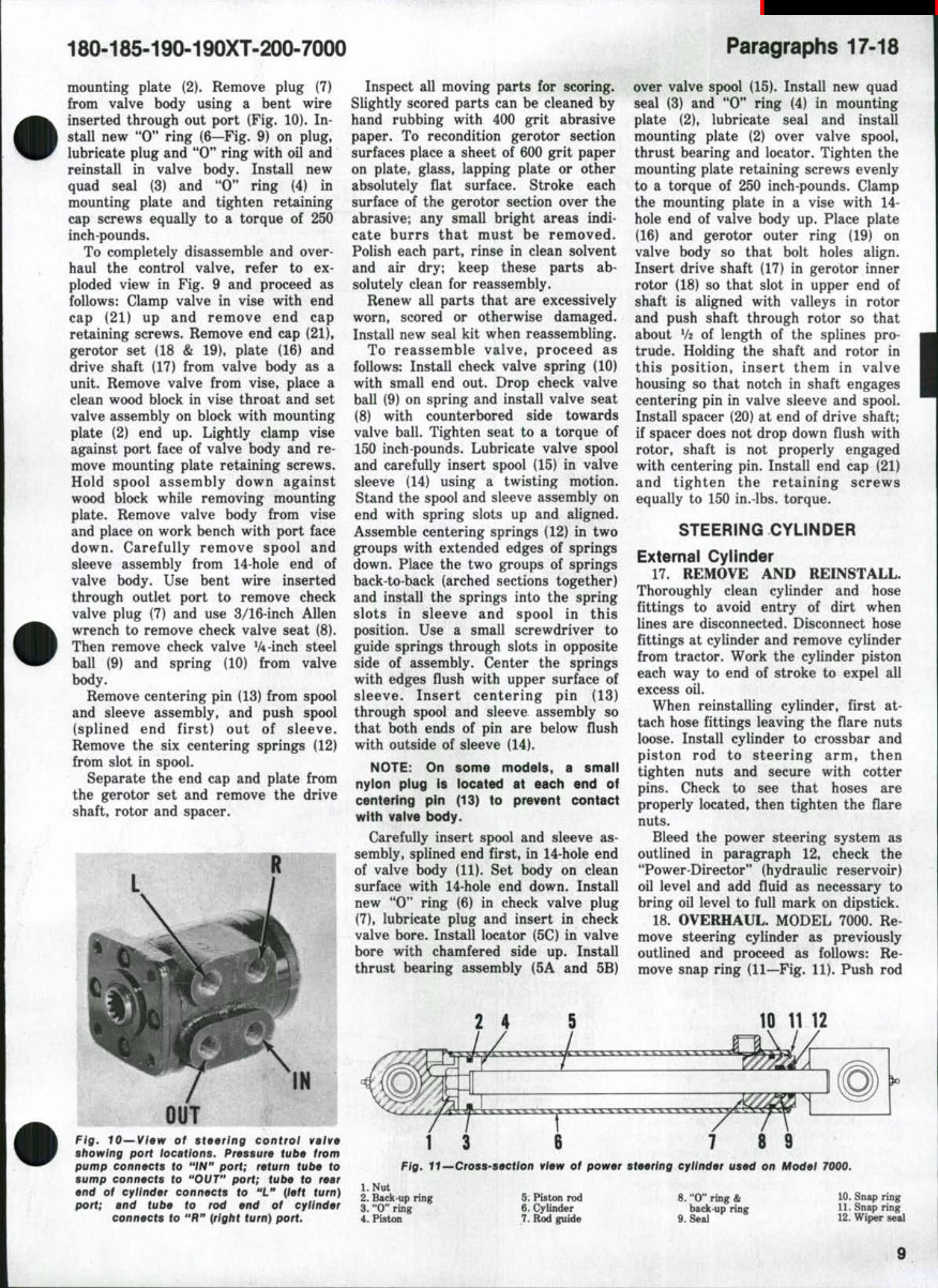
180-185-190-190XT-200-7000 Paragraphs 17-18 mounting plate (2). Remove plug (7) from valve body using a bent wire inserted through out port (Fig. 10). In- stall new "0" ring (6—Fig. 9) on plug, lubricate plug and "0" ring with oil and reinstall in valve body. Install new quad seal (3) and "0" ring (4) in mounting plate and tighten retaining cap screws equally to a torque of 250 inch-pounds. To completely disassemble and over- haul the control valve, refer to ex- ploded view in Fig. 9 and proceed as follows: Clamp valve in vise with end cap (21) up and remove end cap retaining screws. Remove end cap (21), gerotor set (18 & 19), plate (16) and drive shaft (17) from valve body as a unit. Remove valve from vise, place a clean wood block in vise throat and set valve assembly on block with mounting plate (2) end up. Lightly clamp vise against port face of valve body and re- move mounting plate retaining screws. Hold spool assembly down against wood block while removing mounting plate. Remove valve body from vise and place on work bench with port face down. Carefully remove spool and sleeve assembly from 14-hole end of valve body. Use bent wire inserted through outlet port to remove check valve plug (7) and use 3/16-inch Allen wrench to remove check valve seat (8). Then remove check valve V4-inch steel ball (9) and spring (10) from valve body. Remove centering pin (13) from spool and sleeve assembly, and push spool (splined end first) out of sleeve. Remove the six centering springs (12) from slot in spool. Separate the end cap and plate from the gerotor set and remove the drive shaft, rotor and spacer. Inspect all moving parts for scoring. Slightly scored parts can be cleaned by hand rubbing with 400 grit abrasive paper. To recondition gerotor section surfaces place a sheet of 600 grit paper on plate, glass, lapping plate or other absolutely flat surface. Stroke each surface of the gerotor section over the abrasive; any small bright areas indi- cate burrs that must be removed. Polish each part, rinse in clean solvent and air dry; keep these parts ab- solutely clean for reassembly. Renew all parts that are excessively worn, scored or otherwise damaged. Install new seal kit when reassembling. To reassemble valve, proceed as follows: Install check valve spring (10) with small end out. Drop check valve ball (9) on spring and install valve seat (8) with counterbored side towards valve ball. Tighten seat to a torque of 150 inch-pounds. Lubricate valve spool and carefully insert spool (15) in valve sleeve (14) using a twisting motion. Stand the spool and sleeve assembly on end with spring slots up and aligned. Assemble centering springs (12) in two groups with extended edges of springs down. Place the two groups of springs back-to-back (arched sections together) and install the springs into the spring slots in sleeve and spool in this position. Use a small screwdriver to guide springs through slots in opposite side of assembly. Center the springs with edges flush with upper surface of sleeve. Insert centering pin (13) through spool and sleeve assembly so that both ends of pin are below flush with outside of sleeve (14). NOTE: On some models, a smail nyion piug is iocated at each end of centering pin (13) to prevent contact with vaive body. Carefully insert spool and sleeve as- sembly, splined end first, in 14-hole end of valve body (11). Set body on clean surface with 14-hole end down. Install new "0" ring (6) in check valve plug (7), lubricate plug and insert in check valve bore. Install locator (5C) in valve bore with chamfered side up. Install thrust bearing assembly (5A and 5B) over valve spool (15). Install new quad seal (3) and "0" ring (4) in mounting plate (2), lubricate seal and install mounting plate (2) over valve spool, thrust bearing and locator. Tighten the mounting plate retaining screws evenly to a torque of 250 inch-pounds. Clamp the mounting plate in a vise with 14- hole end of valve body up. Place plate (16) and gerotor outer ring (19) on valve body so that bolt holes align. Insert drive shaft (17) in gerotor inner rotor (18) so that slot in upper end of shaft is aligned with valleys in rotor and push shaft through rotor so that about V2 of length of the splines pro- trude. Holding the shaft and rotor in this position, insert them in valve housing so that notch in shaft engages centering pin in valve sleeve and spool. Install spacer (20) at end of drive shaft; if spacer does not drop down flush with rotor, shaft is not properly engaged with centering pin. Install end cap (21) and tighten the retaining screws equally to 150 in.-lbs. torque. STEERING CYLINDER External Cylinder 17. REMOVE AND REINSTALL. Thoroughly clean cylinder and hose fittings to avoid entry of dirt when lines are disconnected. Disconnect hose fittings at cylinder and remove cylinder from tractor. Work the cylinder piston each way to end of stroke to expel all excess oil. When reinstalling cylinder, first at- tach hose fittings leaving the flare nuts loose. Install cylinder to crossbar and piston rod to steering arm, then tighten nuts and secure with cotter pins. Check to see that hoses are properly located, then tighten the flare nuts. Bleed the power steering system as outlined in paragraph 12, check the "Power-Director" (hydraulic reservoir) oil level and add fluid as necessary to bring oil level to full mark on dipstick. 18. OVERHAUL. MODEL 1000. Re- move steering cylinder as previously outlined and proceed as follows: Re- move snap ring (11—Fig, 11). Push rod Fig. 10—View of steering controi vaive showing port locations. Pressure tube from pump connects to "iN" port; return tube to sump connects to "OUT" port; tube to rear end of cylinder connects to "L" {left turn) port; and tube to rod end of cylinder connects to "R** {right turn) port. 1 3 6 7 8 9 Fig. 11—Cross-section view of power steering cylinder used on Model 7000. l.Nut 2. Back-up ring 3. "0" ring 4. Piston 5. Piston rod 6. CyUnder 7. Rod guide 8. "0" ring & back-up ring 9. Seal 10. Sniq) ring 11. Snap ring 12. Wiper seal
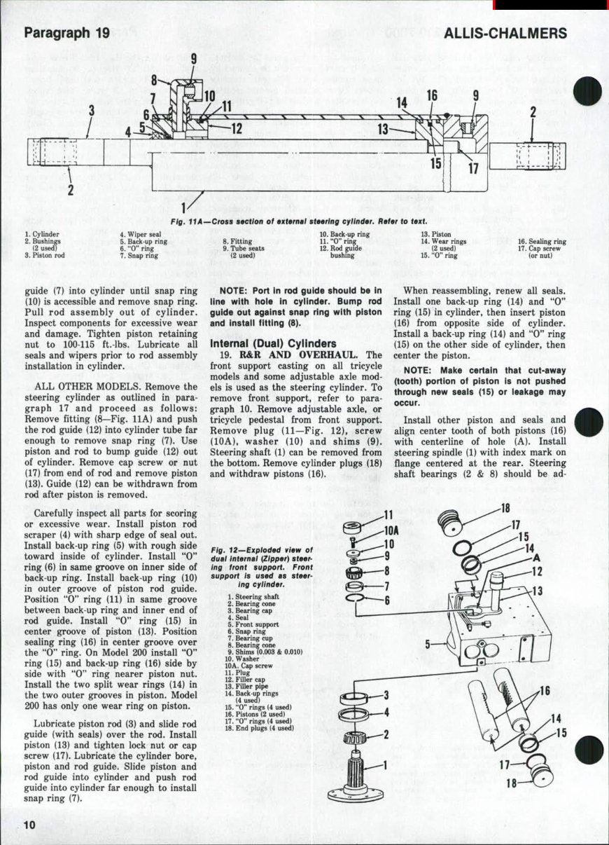
Paragraph 19 ALLIS-CHALMERS 1. Cylinder 2. Bushings (2 used) 3. Piston rod Fig. HA—Cross section of externai steering eyiinder. Refer to text. 4. Wiper seal 5. Back up ring 6. "0" ring 7. Snap ring 8. Fitting 9. Tube seats (2 used) 10. Back up ring 11. "0" ring 12. Rod p i d e bushing 13. Piston 14. Wear rings (2 used) 15. "0" ring 16. Sealing ring 17. Cap screw (or nut) guide (7) into cylinder until snap ring (10) is accessible and remove snap ring. Pull rod assembly out of cylinder. Inspect components for excessive wear and damage. Tighten piston retaining nut to 100-115 ft.-lbs. Lubricate all seals and wipers prior to rod assembly installation in cylinder. ALL OTHER MODELS. Remove the steering cylinder as outlined in para- graph 17 and proceed as follows: Remove fitting (8—Fig. 11 A) and push the rod guide (12) into cylinder tube far enough to remove snap ring (7). Use piston and rod to bump guide (12) out of cylinder. Remove cap screw or nut (17) from end of rod and remove piston (13). Guide (12) can be withdrawn from rod after piston is removed. Carefully inspect all parts for scoring or excessive wear. Install piston rod scraper (4) with sharp edge of seal out. Install back-up ring (5) with rough side toward inside of cylinder. Install "0" ring (6) in same groove on inner side of back-up ring. Install back-up ring (10) in outer groove of piston rod guide. Position "0" ring (11) in same groove between back-up ring and inner end of rod guide. Install "0" ring (15) in center groove of piston (13). Position sealing ring (16) in center groove over the "0" ring. On Model 200 install "0" ring (15) and back-up ring (16) side by side with "0" ring nearer piston nut. Install the two split wear rings (14) in the two outer grooves in piston. Model 200 has only one wear ring on piston. Lubricate piston rod (3) and slide rod guide (with seals) over the rod. Install piston (13) and tighten lock nut or cap screw (17). Lubricate the cylinder bore, piston and rod guide. Slide piston and rod guide into cylinder and push rod guide into cylinder far enough to install snap ring (7). NOTE: Port in rod guide should be in line with hole in cylinder. Bump rod guide out against snap ring with piston and install fitting (8). internai (Duai) Cyiinders 19. R&R AND OVERHAUL. The front support casting on all tricycle models and some adjustable axle mod- els is used as the steering cylinder. To remove front support, refer to para- graph 10. Remove adjustable axle, or tricycle pedestal from front support. Remove plug (11—Fig. 12), screw (lOA), washer (10) and shims (9). Steering shaft (1) can be removed from the bottom. Remove cylinder plugs (18) and withdraw pistons (16). When reassembling, renew all seals. Install one back-up ring (14) and "0" ring (15) in cylinder, then insert piston (16) from opposite side of cylinder. Install a back-up ring (14) and "0" ring (15) on the other side of cylinder, then center the piston. NOTE: Make certain that cut-away (tooth) portion of piston is not pushed through new seais (15) or leakage may occur. Install other piston and seals and align center tooth of both pistons (16) with centerline of hole (A). Install steering spindle (1) with index mark on flange centered at the rear. Steering shaft bearings (2 & 8) should be ad- Fig. 12—Expioded view of dual internal {Zipper) steer- ing front support. Front support is used as steer- ing cylinder. 1. Steering shaft 2. Bearing cone 3. Bearing cap 4. Seal 5. Front support 6. Snap ring 7. Bearing cup 8. Bearing cone 9. Shims (0.003 & 0.010) 10. Washer lOA. Cap screw 11. Plug 12. Filler cap 13. Filler pipe 14. Back up rings (4 used) 15. "0" rings (4 used) 16. Pistons (2 used) 17. "0" rings (4 used) 18. End plugs (4 used) 10
180-185-190-190XT-200-7000 Paragraphs 20-22 justed to a free rolling fit with no end play by varying number and thickness of shims (9). Cap screw (lOA) should be tightened to 130-140 ft.-lbs. torque. Install "0" rings (17) on plugs (18). Refer to paragraph 10 for installation procedure, the same type of oil (AUis- Chalmers "Power Fluid") as used in the hydraulic system should be used in front support. Oil level should be maintained at 2 inches from bottom as measured through breather tube (13). This oil is used to lubricate parts in the front support. Fluid for power steering is contained in Tower-Director" com- partment. Leakage past seals (15) will be noticed by an excessive amount of oil in front support housing. ENGINE AND COMPONENTS R&R ENGINE ASSEMBLY All Models 20. To remove the engine, disconnect all battery ground straps. If engine is to be disassembled, drain oil pan. Remove front support casting as out- lined in paragraph 9 or 10. Unbolt and remove both side rails. NOTE: On models so equipped, detach hydraulic system fiiter from engine left side raii. Disconnect wires and cables from engine electrical units. Disconnect hy- draulic tubes from the pump, remove clamps and reposition tubes away from engine. Disconnect hourmeter cable, shut off fuel supply at tank and discon- nect fuel supply line from gasoline carburetor, diesel injection pump or LP-Gas regulator. On diesel models, disconnect fuel return line, speed con- trol cable and pump shut-off cable. On non-diesel models, disconnect governor control cable and choke cable. NOTE: Depending on reason for engine removal, it may be easier to remove other components from engine at this time. Attach hoist to lift hooks provided at front and rear end of cylinder head, then unbolt and remove engine from torque housing. Reinstall engine and clutch assembly by reversing removal procedures. Bleed the diesel fuel system as outlined in paragraph 60 and, if necessary, bleed the power steering system as outlined in paragraph 12. CYLINDER HEAD All Models 21. REMOVE AND REINSTALL. Drain the cooling system and remove hood top panel and both hood rear side panels. On non-diesel models, shut off fuel at tank and remove inlet manifold, exhaust manifold and carburetor. On diesel models, remove the exhaust manifold. Disconnect fuel lines from injector nozzles and cap all openings as each line is disconnected. NOTE: Aithough not required for removai of cylinder head, it Is re- commended that diesel fuei injector assembiies be removed at this time. The injector nozzle tips protrude through the flat bottom surface of cy- linder head and, if injectors are not removed, extreme care must be taken when removing and handling the re- moved cylinder head. On all models, disconnect upper radiator hose from thermostat housing and remove inlet tube from air cleaner. Disconnect by-pass tube from water pump and thermostat housing, discon- nect wire from temperature gage sending unit and remove thermostat housing. Disconnect bypass tube from water pump and thermostat housing, disconnect wire from temperature gage sending unit and remove thermostat housing. Disconnect breather tube and remove the rocker arm cover. Remove the rocker arm assembly and push rods. Remove cylinder head retaining cap screws and carefully pry cylinder head up off dowel pins located at front and rear of cylinder block. Lift cylinder head from tractor. When reinstalling cylinder head, be sure that gasket surfaces of cylinder head and block are clean and free of burrs. Place new gasket with side marked *THIS SIDE DOWN" against cylinder block and be sure gasket is properly located on the two dowel pins. NOTE: Do not appiy grease or gasicet seaier to gasicet surfaces, block or cylinder head; new gasket is treated with phenoiic sealer. Lubricate the retaining cap screws with motor oii before installing. Install push rods and rocker arm as- sembly. Starting in center and working toward each end, tighten the cylinder head retaining cap screws first to 63-73 ft.-lbs. torque, then to final torque of 150 ft.-lbs. The small rocker arm bracket retaining cap screws on diesel models should be tightened to 28-33 ft.- lbs. torque. On non-diesel models, all rocker arm bracket retaining cap screws should be tightened to 18-20 ft.-lbs. Adjust valve tappet gap cold as outlined in paragraph 28. When installing inlet and exhaust manifolds, observe the following: On diesel models, tighten inlet manifold retaining screws to 18-20 ft.-lbs. torque. On late 190, late 190XT, 200, 7000 and all 180 and all 185 diesel models, the exhaust manifold retaining screws are self-locking type and should be tighten- ed to 30 ft.-lbs. torque. On early 190 and 190XT diesel models, the retaining screws are locked with tab washers and should be tightened to 44-49 ft.-lbs. torque. On all non-diesel models, the two cap screws attaching each end of exhaust manifold should be tightened to 30-33 ft.-lbs. and all other inlet and exhaust manifold attaching screws should be tightened to 44-49 ft.-lbs. Start and run engine for approxi- mately 1 hour until it reaches normal operating temperature (preferably under load); then, retorque cylinder head, inlet manifold and exhaust mani- fold. Valve clearance should be ad- justed to recommended clearance hot as outlined in paragraph 28. VALVES AND SEATS Diesel 22. Inlet valves have a face and seat angle of 30 degrees. A one degree interference angle may be used by machining the seat to 31 degrees. Seat width should be 3/32 inch and can be narrowed using 15 and 60 degree stones. Inlet valves seat directly on cylinder head of early models while a renewable valve seat insert is used on later models. Standard and 0.005-inch oversize seat inserts are available for service. When installing standard in- serts, machine 1.6035-1.6045 diameter counterbore to a depth of 0.3825-0.3835 (measured from gasket surface of cylinder head). Insert should have 0.001-0.003 interference fit in counter- bore. If standard size insert is loose, install 0.005-inch oversize insert. Sur- face of inlet valve head must be recessed at least 0.0345 from cylinder head surface to provide proper clear- ance between valve and piston. Inlet valve stem diameter is 0.3715-0.3720 inch. Exhaust valves have a face and seat angle of 45 degrees on all models ex- cept 200 and 7000 which have a 30 degree seat. A one degree interference angle may be used by machining the seat to 46 degrees on all models except 200 and 7000 which should be main- chined to 31 degrees. Seat width should be 3/32 inch and can be narrowed using 30 and 60 degree stones on all models except models 200 and 7000 which can be narrowed using 15 and 60 degree stones. On early production 190 models and all 180 and 185 models, exhaust valves seat directly in the cylinder head. "One-Ninety** models after engine serial number (2D-03142) and all "XT** and all 200 and 7000 models are 11
This workshop service and repair manual for Allis-Chalmers Model 180, 185, 190, 190XT, 200, 7000 Tractors provides in-depth and highly detailed instructions for vehicle maintenance and repair. It is a valuable resource for both professional mechanics and DIY enthusiasts, offering step-by-step guidance and detailed exploded pictures for efficient completion of various tasks.
The manual covers a wide range of topics including belt pulley, brakes, clutch, cooling system, diesel and gasoline fuel systems, differential, electrical, engine (diesel and non-diesel), final drive, front system, governor, ignition system, LP-gas system, power-director, power shift, power lift system, power take-off, steering system, transmission, and wiring diagrams.
Designed for easy access, this manual is available in PDF format for viewing on Windows PC, Mac, tablet, or smartphone. It can be printed for convenience and reference during vehicle maintenance and repair. With instant access upon payment, there are no shipping costs or waiting for physical delivery, making it a smart and fast solution for obtaining the necessary information.
For those seeking specific manuals, the customer support team can be contacted for assistance in locating the required resources. This comprehensive workshop service manual is the ultimate guide for maintaining and repairing Allis-Chalmers tractors, ensuring the vehicle remains in optimal condition.