

MTD 450 Series Tiller Service & Repair Manual
What's Included?
Fast Download Speeds
Online & Offline Access
Access PDF Contents & Bookmarks
Full Search Facility
Print one or all pages of your manual
Professional Shop Manual
450 Series Tiller
MTD Products Inc - Product Training and Education Department
FORM NUMBER - 769-06021
11/2010
NOTE: These materials are for use by trained technicians who are experienced in the service and repair of outdoor power
equipment of the kind described in this publication, and are not intended for use by untrained or inexperienced individuals.
These materials are intended to provide supplemental information to assist the trained technician. Untrained or inexperi-
enced individuals should seek the assistance of an experienced and trained professional. Read, understand, and follow all
instructions and use common sense when working on power equipment. This includes the contents of the product’s Oper-
ators Manual, supplied with the equipment. No liability can be accepted for any inaccuracies or omission in this publication,
although care has been taken to make it as complete and accurate as possible at the time of publication. However, due to
the variety of outdoor power equipment and continuing product changes that occur over time, updates will be made to these
instructions from time to time. Therefore, it may be necessary to obtain the latest materials before servicing or repairing a
product. The company reserves the right to make changes at any time to this publication without prior notice and without
incurring an obligation to make such changes to previously published versions. Instructions, photographs and illustrations
used in this publication are for reference use only and may not depict actual model and component parts.
© Copyright 2010 MTD Products Inc. All Rights Reserved
For Parts Call 606-678-9623 or 606-561-4983
www.mymowerparts.com

For Parts Call 606-678-9623 or 606-561-4983
www.mymowerparts.com

I
Chapter 1: Introduction 1
About the text format . . . . . . . . . . . . . . . . . . . . . . . . . . . . . . . . . . . . . . . . . . . 1
Safety . . . . . . . . . . . . . . . . . . . . . . . . . . . . . . . . . . . . . . . . . . . . . . . . . . . . . . . 2
Fasteners. . . . . . . . . . . . . . . . . . . . . . . . . . . . . . . . . . . . . . . . . . . . . . . . . . . . 3
Assembly instructions . . . . . . . . . . . . . . . . . . . . . . . . . . . . . . . . . . . . . . . . . . . 3
Understanding model and serial numbers . . . . . . . . . . . . . . . . . . . . . . . . . . . 4
Maintenance chart . . . . . . . . . . . . . . . . . . . . . . . . . . . . . . . . . . . . . . . . . . . . . 5
Chapter 2: Clutch and controls 7
Clutch Operation . . . . . . . . . . . . . . . . . . . . . . . . . . . . . . . . . . . . . . . . . . . . . . . 7
Belt Replacement . . . . . . . . . . . . . . . . . . . . . . . . . . . . . . . . . . . . . . . . . . . . . . 8
Pulley alignment and travel . . . . . . . . . . . . . . . . . . . . . . . . . . . . . . . . . . . . . 10
Idler Pulley Bracket Removal . . . . . . . . . . . . . . . . . . . . . . . . . . . . . . . . . . . . 11
Replacing and Adjusting the Clutch Cable . . . . . . . . . . . . . . . . . . . . . . . . . . 12
Clutch Cable Adjustment . . . . . . . . . . . . . . . . . . . . . . . . . . . . . . . . . . . . . . . 14
Shift lever and rod . . . . . . . . . . . . . . . . . . . . . . . . . . . . . . . . . . . . . . . . . . . . 15
Chapter 3: Engine 17
Engine removal . . . . . . . . . . . . . . . . . . . . . . . . . . . . . . . . . . . . . . . . . . . . . . . 17
Engine installation . . . . . . . . . . . . . . . . . . . . . . . . . . . . . . . . . . . . . . . . . . . . 18
Chapter 4: Transmission Removal 19
Transmission Removal . . . . . . . . . . . . . . . . . . . . . . . . . . . . . . . . . . . . . . . . . 19
Chapter 5: Chain case 25
About this chapter . . . . . . . . . . . . . . . . . . . . . . . . . . . . . . . . . . . . . . . . . . . . . 25
Chain Case Operation: Drive paths . . . . . . . . . . . . . . . . . . . . . . . . . . . . . . . 25
Wheels Reverse . . . . . . . . . . . . . . . . . . . . . . . . . . . . . . . . . . . . . . . . . . . . . . 26
Neutral . . . . . . . . . . . . . . . . . . . . . . . . . . . . . . . . . . . . . . . . . . . . . . . . . . . . . 26
Wheels Forward . . . . . . . . . . . . . . . . . . . . . . . . . . . . . . . . . . . . . . . . . . . . . . 27
Counter Rotation Tilling . . . . . . . . . . . . . . . . . . . . . . . . . . . . . . . . . . . . . . . . . 28
Standard Rotation Tilling . . . . . . . . . . . . . . . . . . . . . . . . . . . . . . . . . . . . . . . 29
Chain Case Separation . . . . . . . . . . . . . . . . . . . . . . . . . . . . . . . . . . . . . . . . 30
Wheel Axle and wheel speed reduction shaft . . . . . . . . . . . . . . . . . . . . . . . . 34
Tine Shaft . . . . . . . . . . . . . . . . . . . . . . . . . . . . . . . . . . . . . . . . . . . . . . . . . . . 37
Main Shaft Assembly . . . . . . . . . . . . . . . . . . . . . . . . . . . . . . . . . . . . . . . . . . 40
Counter shaft . . . . . . . . . . . . . . . . . . . . . . . . . . . . . . . . . . . . . . . . . . . . . . . . 43
Detent shaft . . . . . . . . . . . . . . . . . . . . . . . . . . . . . . . . . . . . . . . . . . . . . . . . . 45
Input shaft . . . . . . . . . . . . . . . . . . . . . . . . . . . . . . . . . . . . . . . . . . . . . . . . . . . 46
Shift arm . . . . . . . . . . . . . . . . . . . . . . . . . . . . . . . . . . . . . . . . . . . . . . . . . . . . 49
Inspection . . . . . . . . . . . . . . . . . . . . . . . . . . . . . . . . . . . . . . . . . . . . . . . . . . . 53
Final Assembly Notes . . . . . . . . . . . . . . . . . . . . . . . . . . . . . . . . . . . . . . . . . . 55
Chapter 6: tines 63
Tines . . . . . . . . . . . . . . . . . . . . . . . . . . . . . . . . . . . . . . . . . . . . . . . . . . . . . . . 63
Accessing the tines . . . . . . . . . . . . . . . . . . . . . . . . . . . . . . . . . . . . . . . . . . . . 63
Table of Contents
For Parts Call 606-678-9623 or 606-561-4983
www.mymowerparts.com

II
For Parts Call 606-678-9623 or 606-561-4983
www.mymowerparts.com

Introduction
1
Professional Service Manual Intent: This manual is intended to provide service dealers with repair and overhaul
procedures for the 450 series tiller..
Disclaimer: The information contained in this manual is correct at the time of writing. Both the product and the infor-
mation about the product are subject to change without notice.
About the text format
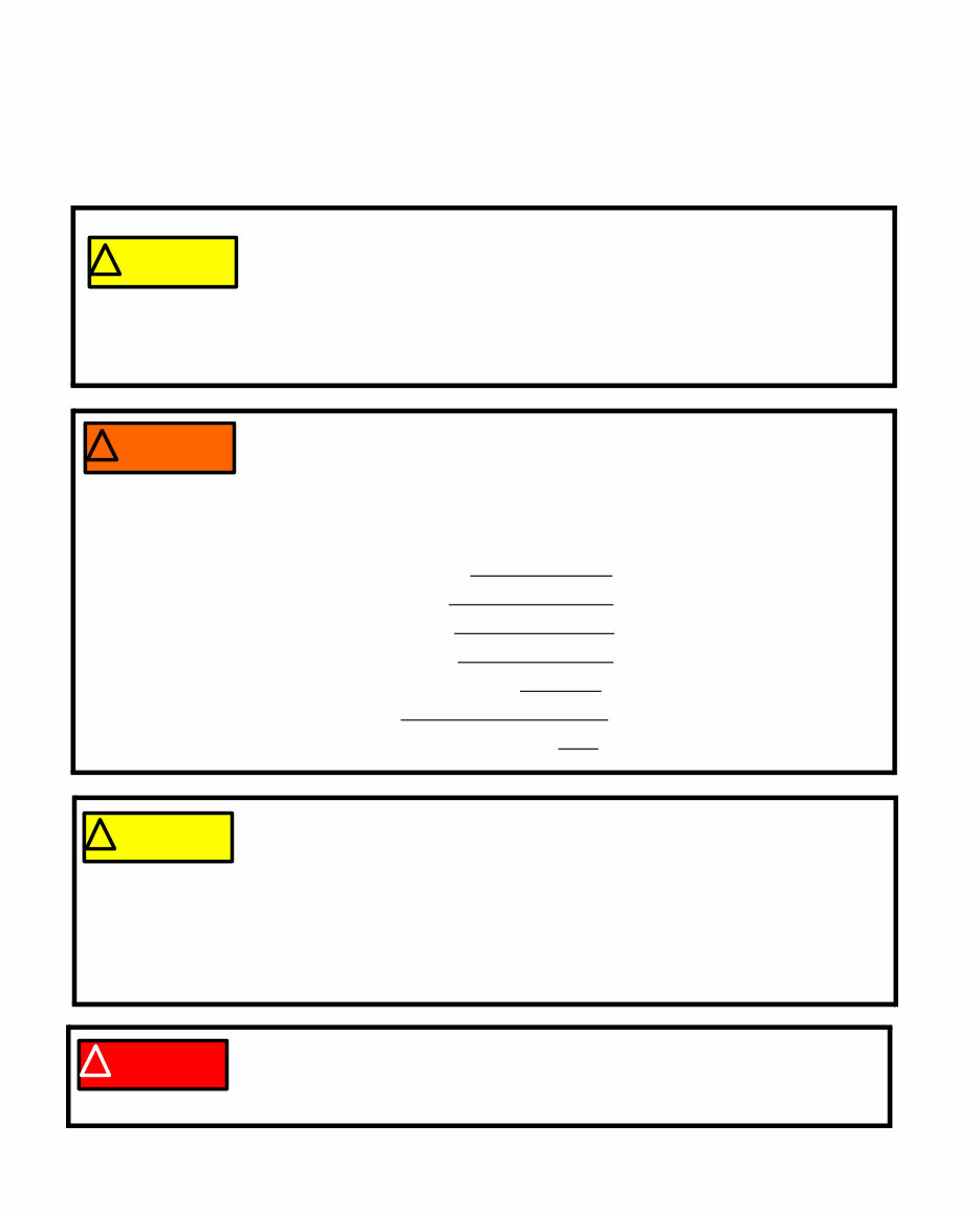
Certain flags and key words are used to indicate the nature of the text that accompanies them. They are as follows:
CAUTION: Indicates a potentially hazardous situation that, if not avoided, may result
in minor or moderate injury. It may also be used to alert against unsafe practices.
WARNING: Indicates a potentially hazardous situation that, if not avoided, could
result in death of serious injury.
DANGER: Indicates an imminently hazardous situation that, if not avoided, will result
in death or serious injury. This signal word is to be limited to the most extreme situa-
tions.
NOTE: “NOTE” is used to point-out helpful information that may not fit as a step in a procedure.
1. Numbered steps indicate specific things that should be done, and the order in which they should be done.
1a. Sub steps will be lettered and nested within steps. Two or more sub steps may be combined to describe
the actions required to complete a step.
• Bullet points: Indicate sub-steps or points of interest, without implying order or relative importance.
Disclaimer: This manual is intended for use by trained, professional technicians.
• Common sense in operation and safety is assumed.
• In no event shall MTD be liable for poor text interpretation, or poor execution of the procedures described
in the text.
• If the person using this manual is uncomfortable with any procedures they encounter, they should seek
the help of a qualified technician.
CHAPTER 1: INTRODUCTION ! WARNING ! DANGER ! CAUTION
For Parts Call 606-678-9623 or 606-561-4983
www.mymowerparts.com
450 Series Tillers
2
Safety
This Service Manual is meant to be used along with the Operator’s Manual. Read the Operator’s Manual and
familiarize yourself with the safety and operational instructions for the equipment being worked on. Keep a copy of
the Operator’s Manual for quick reference. Operator’s manuals may be viewed for free at the brand support website.
It will be necessary to have the complete model and serial number for the equipment.
• Be prepared in case of emergency:
Keep a fire extinguisher nearby
Keep a first aid kit nearby
Keep emergency contact numbers handy
• Replace any missing or damaged safety labels on shop equipment.
• Replace any missing or damaged safety labels on equipment being serviced.
• Grooming and attire:
Do not wear loose fitting clothing that may become entangled in equipment.
Long hair should be secured to prevent entanglement in equipment.
Jewelry is best removed.
• Protective gear: includes, but is not limited to
Clear eye protection while working around any machinery
Protective gloves where necessary
Armored footwear when working around any machinery
Hearing protection in noisy environments
Chemically resistant gloves when working with chemicals or solvents
Respirator when working with chemical or solvents
Appropriate tinted eye protection when cutting or welding ! WARNING ! CAUTION
• Remember that some hazards have a cumulative effect. A single exposure may
cause little or no harm, but continual or repeated exposure may cause very seri-
ous harm.
• Clean spills and fix obviously dangerous conditions as soon as they are noticed.
• Lift and support heavy objects safely and securely.
• Be aware of your surroundings and potential hazards that are inherent to all
power equipment. All the labels in the world cannot protect a technician from an
instant of carelessness.
Exhaust fumes from running engines contain carbon monoxide (CO). Carbon monox-
ide is a colorless odorless gas that is fatal if inhaled in sufficient quantity. Only run engines
in well ventilated areas. If running engines indoors, use an exhaust evacuation system
with adequate make-up air ventilated into the shop. ! DANGER ! CAUTION
For Parts Call 606-678-9623 or 606-561-4983
www.mymowerparts.com

Introduction
3
Fasteners
• The fasteners used on the equipment described in this manual and the engine that powers it, are a combi-
nation of metric and fractional inch. For this reason, wrench sizes are frequently identified in the text, and
measurements are given in U.S. and metric scales.
• If a fastener has a locking feature that has worn, replace the fastener or apply a small amount of releas-
able thread locking compound such as Loctite® 242 (blue).
• Some fasteners like cotter pins are single-use items that are not to be reused. Other fasteners such as
lock washers, retaining rings, and internal cotter pins (hairpin clips) may be reused if they do not show
signs of wear or damage. This manual leaves that decision to the judgement of the technician.
Assembly instructions
• Torque specifications may be noted in the part of the text that covers assembly. They may be summa-
rized in tables along with special instructions regarding locking or lubrication. Whichever method is more
appropriate will be used. In many cases, both will be used so that the manual is handy as a quick-refer-
ence guide as well as a step-by-step procedure guide that does not require the user to hunt for informa-
tion.
• Lubricant quantity and specification may be noted in the part of the text that covers maintenance, and
again in the section that covers assembly. They may also be summarized in tables along with special
instructions. Whichever method is more appropriate will be used. In many cases, the information will be
found in several places in the manual so that the manual is handy as a quick-reference guide as well as a
step-by-step procedure guide that does not require the user to hunt for information.
• The level of assembly instructions provided will be determined by the complexity of reassembly, and by
the potential for damage or unsafe conditions to arise from mistakes made in assembly.
• Some instructions may refer to other parts of the manual for subsidiary procedures. This avoids repeating
the same procedure two or three times in the manual.
For Parts Call 606-678-9623 or 606-561-4983
www.mymowerparts.com

450 Series Tillers
4
Understanding model and serial numbers
The model number of a the 450 series tiller described in this manual is 21AA453B000.
The break down of what the model number means is as follows:
• 21 - - - - - - - - - - - - - - -indicates that this is a tiller
• - - -A- - - - - - - - - - - - - - indicates the sales revision
• - - - - A - - - - - - - - - - -indicates the tire size
• - - - - - - 4 - - - - - - - - - -indicates the tiller series
• - - - - - - - 5 - - - - - - - - -indicates the transmission
• - - - - - - - - - 3B - - - - - -indicates the engine
• - - - - - - - - - - - - 000 - -indicates the customer
The serial number is 1J059P10005. The serial number reads as follows:
• 1 - - - - - - - - - - - - - - - -engineering level
• - J - - - - - - - - - - - - - - -month of production (J = October)
• - - 05 - - - - - - - - - - - - -day of the month
• - - - - 9 - - - - - - - - - - - -last digit of the year
• - - - - - P. - - - - - - - - - - -plant it was built in
• - - - - - - -1 - - - - - - - - - -assembly line number
• - - - - - - - - 0005- - - - - -number of unit built
Additional technical and service information may also be available to our company authorized service center per-
sonnel through our company corporate offices, regional parts distributors and regional service center field support
personnel. Please contact the designated support office in your area or our corporate offices directly should further
service information be needed.
MTD Products LLC
P.O. Box 368022
Cleveland, OH 44136
Telephone: (800) 800-7310
www.mtdproducts.com
Figure 1.1
The 450 series tiller
The 450 series tiller is a chain case tiller line that was
first introduced for the 1999 model year. This is a rear tine,
dual direction tiller. This tiller has a chain case transmission
that features:
• Ability to till in standard and reverse directions.
• Forward wheel drive
• Reverse wheel drive
• Neutral to disengage the wheels.
• 16” ag tires
For Parts Call 606-678-9623 or 606-561-4983
www.mymowerparts.com

Introduction
5
Maintenance chart
Maintenance item Each use Each 25 hrs. use Each 50 hrs. use
Check engine oil
*
Check air filter
*
Check for loose/broke tines
*
Check & gap spark plug Replace if worn
*
Check cooling fins After prolonged storage
Check/clean spark arrestor
*
Change oil
*
Note on oil: Change oil after first 5 hrs of use and before prolonged storage
Change air filter
*
Note on air filter Air filter and pre-filter life vary dramatically with operating conditions
Drain or preserve fuel Before prolonged storage
Fog or lube cylinder Before prolonged storage
Rotate engine to TDC Before prolonged storage
Remove wheels/lube wheel shaft Once a year
Remove tines/lube tine shaft Once a year
Engine RPM 3500 + 100
For Parts Call 606-678-9623 or 606-561-4983
www.mymowerparts.com

450 Series Tillers
6
For Parts Call 606-678-9623 or 606-561-4983
www.mymowerparts.com
You're Reading a Preview
What's Included?
Fast Download Speeds
Online & Offline Access
Access PDF Contents & Bookmarks
Full Search Facility
Print one or all pages of your manual
$31.99
$41.99
Viewed 65 Times Today


Secure transaction
What's Included?
Fast Download Speeds
Online & Offline Access
Access PDF Contents & Bookmarks
Full Search Facility
Print one or all pages of your manual
$31.99
$41.99
Get the MTD 450 Series Tiller Service & Repair Manual to access comprehensive technical information for maintaining and repairing your equipment. Whether you're a professional mechanic or a DIY enthusiast, this manual provides valuable insights into the inner workings of the MTD 450 Series Tiller.


