

Stihl FS 120 200 300 350 400 450 & FR 350 450 Brushcutters Workshop Service Repair Manual
What's Included?
Fast Download Speeds
Online & Offline Access
Access PDF Contents & Bookmarks
Full Search Facility
Print one or all pages of your manual

STIHL FR 350, 450 2003-04
STIH)
STIHL FS 120, 200, 300, 350, 400, 450,
STIH)
chodina@live.co.uk chodina@live.co.uk

1. Introduction 2
2. Specifications 3
2.1 Engine 3
2.2 Fuel System 3
2.3 Ignition System 4
2.4 Gearhead 4
2.5 Special Accessories 4
2.5.1 For User 4
2.5.2 For Service 4
2.6 Tightening Torques 5
3. Clutch 7
3.1 Removing and Installing 7
3.2 Clutch Carrier 8
4. Engine 9
4.1 Exhaust Muffler/
Spark Arresting Screen 9
4.2 Leakage Test 10
4.2.1 Preparations 10
4.2.2 Pressure Test 11
4.2.3 Vacuum Test 11
4.3 Oil Seals 12
4.4 Exposing the Cylinder 13
4.5 Cylinder and Piston 14
4.5.1 Removal 14
4.5.2 Installation 15
4.6 Piston Rings 17
4.7 Crankcase 17
4.7.1 Removing Crankshaft 17
4.7.2 Installing Crankshaft 20
4.8 Decompression Valve 23
5. Ignition System 23
5.1 Spark Plug Boot 23
5.2 Ignition Lead
(FS 400/450, FR 450) 24
5.3 Ignition Module 25
5.3.1 Ignition Timing 26
5.3.2 Removing and Installing
(FS 120...350, FR 350) 26
5.3.3 Removing and Installing
(FS 400/450, FR 450) 27
5.4 Flywheel 28
5.5 Short Circuit Wire 29
6. Rewind Starter 30
6.1 General 30
6.2 Rewind Spring 30
6.2.1 Replacing 30
6.2.2 Tensioning 31
6.3 Starter Rope/Starter
Grip (ElastoStart) 32
7. Throttle Control 33
7.1 Throttle Trigger/Interlock
Lever (Bike Handle) 33
7.2 Contact Springs/Detent
Spring in Control Handle
(Bike Handle) 34
7.3 Throttle Trigger/Interlock
Lever (Loop Handle) 34
7.4 Slide Control
(Loop Handle) 35
7.5 Throttle Cable 36
7.5.1 Replacing 36
7.5.2 Adjusting 37
8. Fuel System 38
8.1 Air Filter 38
8.2 Carburetor 39
8.2.1 Removing and Installing
(FS 120...350, FR 350) 39
8.2.2 Removing and Installing
(FS 400/450, FR 450) 40
8.2.3 Leakage Test 41
8.2.4 Adjusting
(three screws) 42
8.2.5 Adjusting
(one screw) 43
8.3 Tank Vent 44
8.4 Pickup Body 44
8.5 Fuel Tank/
Hoses 45
8.6 Manual
Fuel Pump 47
9. AV System 47
9.1 Repair
(FS 120/200) 47
9.2 Repair
(FS 300...450) 48
9.3 Repair
(FR 350/450) 50
10. Shaft 51
10.1 Bike Handle
(FS 120/200) 51
10.2 Bike Handle
(FS 300...450) 51
10.3 Loop Handle 52
10.4 Drive Shaft/
Flexible Liner 52
10.5 Flexible Shaft
(FR 350/450) 53
10.6 Drive Tube 54
10.7 Housing
(FR 350/450) 56
11. Cutting Tool
Drive 56
11.1 Gearhead 56
11.2 Clutch Drum 57
12. Support Frame
(FR 350/450) 58
12.1 Repair 58
13. Special Servicing
Tools and Aids 59
13.1 Special Servicing Tools 59
13.2 Servicing Aids 61
© 2000, Andreas Stihl AG & Co., Waiblingen
CONTENTS
qS
FS 120, 200, 300, 350, 400, 450, FR 350, 450 1
chodina@live.co.uk chodina@live.co.uk
This service manual contains de-
tailed descriptions of all the repair
and servicing procedures specific
to this power tool series.
There are separate handbooks for
servicing procedures for stand-
ardized parts and assemblies that
are installed in several STIHL
power tool models. Reference is
made to these handbooks in the
appropriate chapters in this
manual.
As the design concept of models
FS 120, FS 200, FS 300, FS 350,
FS 400, FS 450 and FR 350, FR
450 is almost identical, the descrip-
tions and servicing procedures in
this manual generally apply to all
models. Differences are described
in detail.
You should make use of the
illustrated parts lists while carrying
out repair work. They show the
installed positions of the individual
components and assemblies.
Refer to the latest edition of the
relevant parts list to check the part
numbers of any replacement parts
needed.
Parts lists on microfiche and CD-
ROM are always more up to date
than printed lists.
A fault on the power tool may have
several causes. Consult the
troubleshooting charts for all as-
semblies in the "Standard Repairs,
Troubleshooting" handbook.
Refer to the "Technical Informa-
tion" bulletins for engineering
changes which have been intro-
duced since publication of this
service manual. Technical informa-
tion bulletins also supplement the
parts list until a revised edition is
issued.
The special servicing tools mentio-
ned in the descriptions are
listed in the last chapter of this
manual.
Use the part numbers to identify
the tools in the "STIHL Special
Tools" manual.
The manual lists all special
servicing tools currently available
from STIHL.
Symbols are included in the text
and pictures for greater clarity.
The meanings are as follows:
In the descriptions:
• = Action to be taken as
shown in the illustration
(above the text)
- = Action to be taken that
is not shown in the
illustration
(above the text)
In the illustrations:
= Pointer
= Direction of movement
Service manuals and all technical
information bulletins describing
engineering changes are intended
exclusively for the use of STIHL
servicing dealers. They must not
be passed to third parties.
Servicing and repairs are made
considerably easier if the machine
is mounted on assembly stand (2)
5910 890 3100 with the aid of
clamp (1) 5910 890 8800.
Secure the clamp to the assembly
stand with two washers and two
M8 nuts.
Servicing and repairs to the power-
head are considerably easier if it is
mounted on assembly stand (2)
5910 890 3100 with the aid of
clamping plate (1) 5910 890 2101.
First remove the clutch housing
and secure the powerhead to the
stand with two M6x20 and two
M10x25 hex. head screws.
The machine or powerhead can
then be swivelled to the best posi-
tion for the ongoing repair and this
leaves both hands free.
Always use original STIHL
replacement parts.
They can be identified by the
STIHL part number,
the
and the STIHL parts symbol
The symbol may appear alone on
small parts.
1. INTRODUCTION
250RA228
1
2
VA
250RA227 VA
2
1
2 FS 120, 200, 300, 350, 400, 450, FR 350, 450
chodina@live.co.uk chodina@live.co.uk

2.1 Engine
STIHL single cylinder two-stroke engine with special impregnated cylinder bore
FS 120/300 FS 200/350 FS 400 FS 450
FR 350 FR 450
Displacement: 30.8 cm
3
36.3 cm
3
40.2 cm
3
44.3 cm
3
1.88 cu.in 2.21 cu.in 2.45 cu.in 2.70 cu.in
Bore: 35 mm 38 mm 40.0 mm 42.0 mm
1.38 in 1.49 in 1.57 in 1.65 in
Stroke: 32 mm 32 mm 32 mm 32 mm
1.26 in 1.26 in 1.26 in 1.26 in
Power output: 1.3 kW (1.8 bhp) 1.6 kW (2.2 bhp) 1.9 kW (2.6 bhp) 2.1 kW (2.8 bhp)
at 9,000 rpm
Max. permissible engine speed
without cutting tool
(cut-off speed): 12,500 ± 1000 rpm 12,500 ± 800 rpm
Idle speed: 2,800 rpm
Bearings: Crankshaft supported in heavy-duty ball bearings, needle cages on
small and big ends
Piston pin diameter: 10 mm (0.39 in)
Rewind starter: ElastoStart
Pawls: Single pawl system
Reserve pull on rope rotor: min. 1/2 turn
Starter rope: 3.0 mm (0.12 in) dia. x 800 mm (31.5 in)
Clutch: Centrifugal clutch without linings
Clutch engages at: 4,300 rpm
Crankcase leakage
test
at gauge pressure: 0.5 bar (7.25 psi)
under vacuum: 0.5 bar (7.25 psi)
2.2 Fuel System
Carburetor: Diaphragm carburetor
Standard setting on carburetors
with three adjusting screws
High speed screw H: Open approx. 1 turn
Low speed screw L: Open approx. 1 turn
Carburetor leakage test
at gauge pressure: 0.8 bar (11.6 psi)
Function of tank vent
at gauge pressure: ≤ 0.3 bar (4.35 psi)
under vacuum: ≤ 0.05 bar (0.725 psi)
Fuel tank capacity: 0.64 l (1.35 US pt) 0.68 l (1.44 US pt)
Octane rating: min. 90 RON (US/CAN; pump octane min. 87)
Fuel mixture: Regular brand name gasoline
and two-stroke engine oil
Mix ratio: 50:1 with STIHL two-stroke engine oil
25:1 with other brand name two-stroke, air-cooled engine oils
Air filter: Paper filter
2. SPECIFICATIONS
FS 120, 200, 300, 350, 400, 450, FR 350, 450 3
chodina@live.co.uk chodina@live.co.uk

2.3 Ignition System Type: Electronic magneto
ignition (breakerless)
with integral trigger unit
and electronic speed
governor
Air gap: 0.2 - 0.5 mm (0.008 - 0.020 in)
Length of ignition lead: 305 mm * (12 in)*
Spark plug (suppressed): Bosch WSR 6F,
NGK BPMR 7 A or
Champion RCJ 6Y
Electrode gap: 0.5 mm (0.020 in)
Splark plug thread: M14x1.25
Length of thread: 9.5 mm (0.37 in)
2.4 Gearhead Type: Spiral-toothed
bevel gear drive
Gear ratio: 1:1.4 **
1:1.235
Bearings: Deep groove ball bearings
Lubrication: STIHL gear lubricant 0781 120 1117
(7 g / 0.25 oz)
2.5 Special Accessories
2.5.1 For User Full harness
Safety glasses
Transport guard for
metal cutting tools
STIHL gear lubricant (80 g/3 oz tube) 0781 120 1109
STIHL gear lubricant (80 g/3 oz tube) 0781 120 1117
2.5.2 For Service Carburetor parts kit 4134 007 1060
Set of gaskets
for FS 120, 200, 300, 350, FR 350 4134 007 1050
Set of gaskets
for FS 400, 450, FR 450 4128 007 1050
* FS 400/450 only
** FS 120, 200, 350 and 450
4 FS 120, 200, 300, 350, 400, 450, FR 350, 450
chodina@live.co.uk chodina@live.co.uk

DG and P screws (Plastoform) are used in polymer and lightmetal components. These screws form a perma-
nent thread when they are installed for the first time. They can be removed and installed as often as necessary
without detrimentally affecting the strength of the screwed assembly, providing the specified tightening torque is
observed. For this reason it is essential to use a torque wrench.
Fastener Thread For component Torque Remarks
size Nm lbf.ft
Self-tapping screw IS-B3.5x6.5 Rewind spring/fan housing 1.5 1.1
Self-tapping screw IS-B4.2x9.5 Muffler/spark arresting screen 2.5 1.8 1) 2)
Spline screw IS-DG4x20 Ignition module/crankcase 4.5 3.3 3) 4) 5)
Spline screw IS-DG5x24 Ignition module/crankcase 6.0 4.4 1) 2)
Spline screw IS-DG5x12 AV sleeve/drive tube (fixing screw) 2.5 1.8 3)
Spline screw IS-DG5x12 Guard ring/gear housing 5.0 3.7 1) 4)
Spline screw IS-DG5x20 Fan housing/crankcase 6.0 4.4
Spline screw IS-DG5x20 Fan housing/shroud/crankcase 6.0 4.4
Spline screw IS-DG5x20 Carburetor housing/crankcase/
cylinder 6.0 4.4
Spline screw IS-DG5x20 Filter housing/ground wire/
crankcase 6.0 4.4
Spline screw IS-DG5x20 Ground wire/crankcase 6.0 4.4 1) 2)
Spline screw IS-DG5x26 Fuel tank/crankcase 6.0 4.4
Spline screw IS-DG5x24 Bracket/crankcase 6.0 4.4 1)
Spline screw IS-DG5x20 Shroud/clutch housing 6.0 4.4
Spline screw IS-DG5x26 Guard plate/fuel tank/
crankcase 6.0 4.4 1) 2)
Spline screw IS-DG5x28 Cylinder/crankcase 10.5 7.5
Spline screw IS-DG5x24 Muffler/crankcase 8.5 6.3
Spline screw IS-DG5x24 Muffler/cylinder 8.5 6.3
Spline screw IS-DG5x24 Crankcase 8.5 6.3
Spline screw IS-DG5x24 Clutch housing/crankcase 8.5 6.3 1) 2) 4) 5)
Spline screw IS-DG5x24 Clutch housing/crankcase 6.0 4.4 3)
Spline screw IS-DG6x28 Clutch housing/drive tube 12.0 8.8 1) 6)
Spline screw IS-DG5x24 Clutch housing/drive tube 8.5 6.3 4)
Spline screw IS-DG5x24 Gear housing/drive tube 8.5 6.3 2) 3) 5)
Spline screw IS-DG5x25 Gear housing/drive tube
Stage 1 1.5 1.1 1) 4)
Stage 2 7.5 5.5 1) 4)
Collar nut M5 Filter housing/carburetor housing 3.5 2.6
Collar screw M5/P6 Carburetor housing 4.0 3.0
Spline screw IS-M5x12 Clamp/control handle/
drive tube (loop handle) 2.0 1.5 3) 4)
Spline screw IS-M5x16 AV sleeve/drive tube (clamp screw) 5.5 4.0 3)
Spline screw IS-M5x12 Clamp/control handle/drive tube 2.0 1.5 2) 5)
Spline screw IS-M5x16 Clamp/drive tube (for harness) 4.5 3.3 3)
Spline screw IS-M5x30 Control handle (bike handle) 2.0 1.5 6)
2.6 Tightening Torques
FS 120, 200, 300, 350, 400, 450, FR 350, 450 5
chodina@live.co.uk chodina@live.co.uk

Fastener Thread For component Torque Remarks
size Nm lbf.ft
Spline screw IS-M6x25 Clamp/loop handle 4.5 3.3 3)
Spline screw IS-M6x25 Support/drive tube 6.0 4.4 1) 4) 6)
Spline screw IS-M6x35 Clamp moldings/support block
(handle support/bike handle) 4.5 3.3 3)
M8 Carrier 24.0 17.7
Spline screw IS-M6x18 Clutch shoe/carrier 12.0 8.8
M8 Flywheel 32.0 23.6
M10 Decompression valve 14.0 10.3 1) 2) 4) 5)
M14x1.25 Spark plug 20.0 15.0
Screw plug M11x10 Gearhead 8.5 6.3
Spline screw IS-M5x14 Filter cover/filter housing 6.0 4.4 1) 2)
Plastoform screw IS-P4x16 Control handle/handle moldings 1.0 0.75
Collar screw IS-P3.5x10.6 Detent spring/slide control
(bike handle) 1.1 0.80 1) 3) 4)
Nut M12x1.5 L Cutting tool 25.0 18.5
Spline screw IS-M5x16 Cutting tool deflector/gearhead 4.3 3.2
Spline screw IS-M6x14 Spring/support plate 10.0 7.5 2) 5)
Spline screw IS-M6x25 Housing/shaft clamp screw 4.5 3.3 2) 5)
Spline screw IS-M6x14 Bearing housing/support frame 10.0 7.5 2) 5)
Spline screw IS-M10x20 Support plate/ball bearing/
support frame 20.0 15.0 2) 5)
Use the following procedure to fit a DG or P screw in an existing thread:
– Place the DG or P screw in the hole and rotate it counterclockwise until it drops down slightly.
– Tighten the screw clockwise to the specified torque.
This procedure ensures that the screw engages properly in the existing thread and does not form a new thread.
1) FS 400/450
2) FR 450
3) FS 120/200
4) FS 300/350
5) FR 350
6) with washer
Note: Power screwdriver speed settings for polymer: Plastoform screws max. 600 rpm
DG screws max. 500 rpm
6 FS 120, 200, 300, 350, 400, 450, FR 350, 450
chodina@live.co.uk chodina@live.co.uk
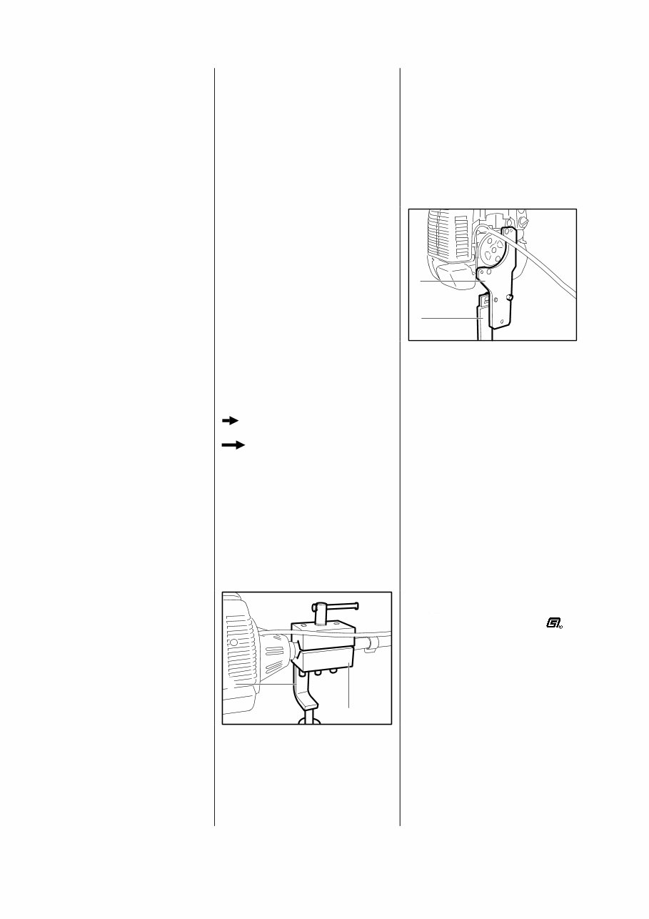
Removal
Troubleshooting chart - see
"Standard Repairs, Trouble-
shooting" handbook.
- Remove clutch housing -
see 9.1 or 11.2.
All models
• Inspect clutch drum. There
should be no scores or signs of
excessive wear.
Important: If there are signs of
serious wear on the inside
diameter, fit a new clutch drum -
see 11.2.
- Remove the shroud - see 4.1.
- Pull off the spark plug boot.
- Unscrew the spark plug.
FS 120...350, FR 350
• Fit locking strip (1)
0000 893 5903.
FS 400/450, FR 450
• Fit locking strip (1)
4221 893 5900.
• Take out screws (1).
• Remove cover (2).
• Remove clutch shoes with
bushings.
• Take bushings out of the clutch
shoes.
• Twist the clutch shoes and
detach the springs.
Important: Clutch shoes and
springs must always be replaced
in pairs.
3. CLUTCH
3.1 Removing and Installing
250RA001
1
VA
250RA002
1
VA
250RA004
1
1
2
VA
250RA003 VA
250RA005 VA
250RA230 VA
250RA229 VA
FS 120, 200, 300, 350, 400, 450, FR 350, 450 7
chodina@live.co.uk chodina@live.co.uk
Installation
• Fit clutch shoes with springs and
bushings so that the arrows point
counterclockwise.
• Fit cover in position.
• Insert screws and tighten down
to 12 Nm (8.8 lbf.ft).
- Pull locking strip out of cylinder.
- Fit spark plug and tighten down
to 20 Nm (15 lbf.ft).
Important: If the spark plug
comes with a separate terminal
nut, always fit the nut on the
thread and tighten it down
securely.
- Fit the boot on the spark plug.
- Fit the shroud - see 4.1.
- Fit clutch housing -
see 9.1 or 11.2.
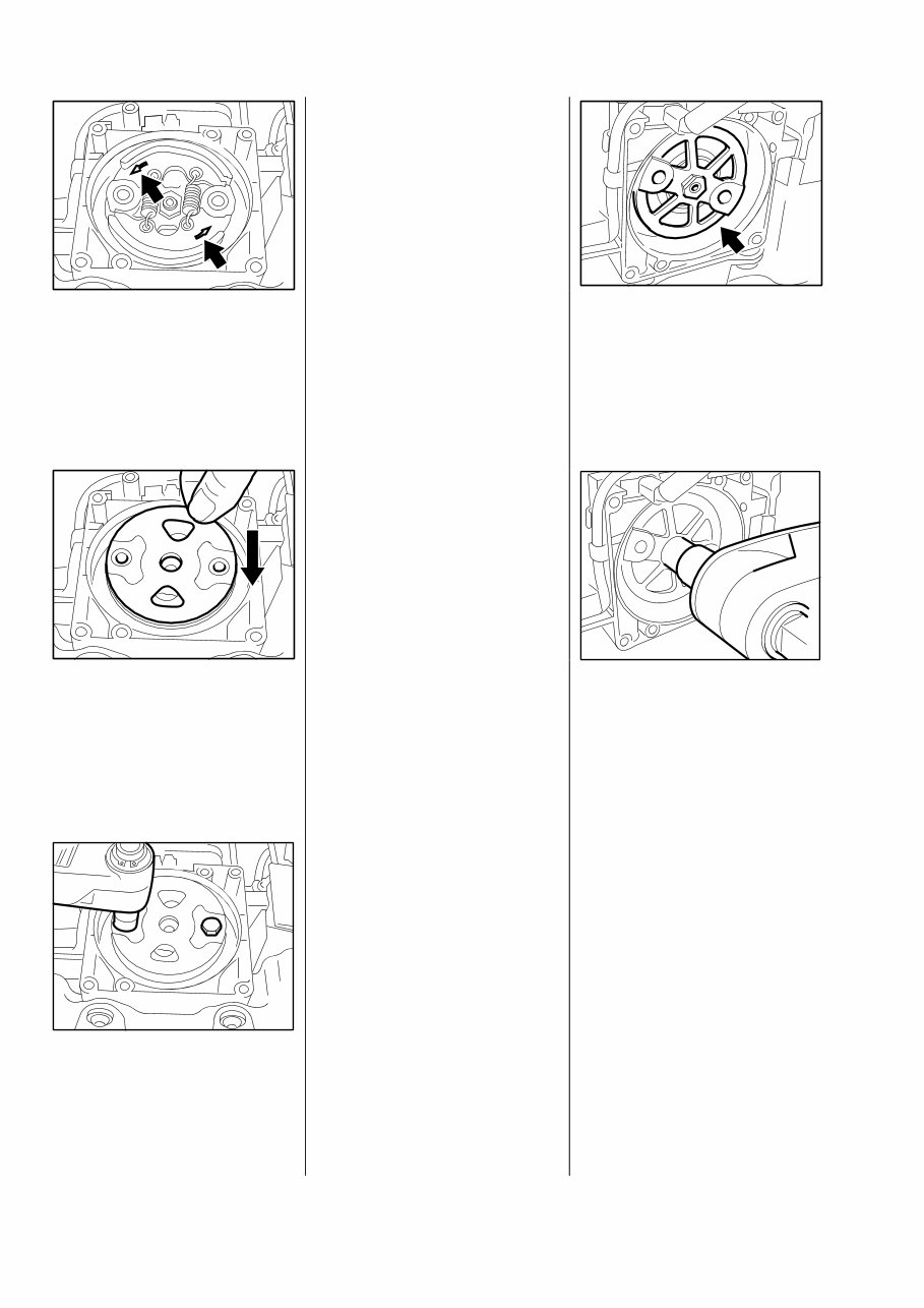
- Remove clutch - see 3.1.
• Unscrew carrier from end of
crankshaft.
• Fit the carrier and tighten it
down to 24 Nm (17.7 lbf.ft).
- Install the clutch - see 3.1.
3.2 Clutch Carrier
250RA232 VA 250RA231 VA
250RA234 VA
250RA235 VA
250RA233 VA
8 FS 120, 200, 300, 350, 400, 450, FR 350, 450
chodina@live.co.uk chodina@live.co.uk
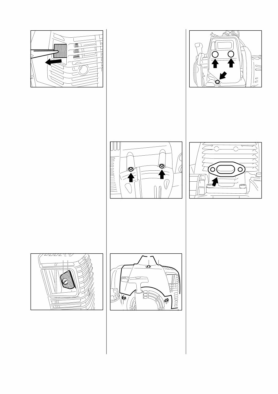
Troubleshooting chart - see
"Standard Repairs, Trouble-
shooting" handbook.
Spark arresting screen
FS 120...350, FR 350
• Pull spark arresting screen out of
the muffler.
- Clean or replace spark arresting
screen if necessary.
FS 400/450, FR 450
• Take out the screw (1).
• Pull spark arresting screen (2)
out of the muffler.
- Clean or replace spark arresting
screen if necessary.
- Tighten down screw to 2.5 Nm
(1.8 lbf.ft).
Muffler
FS 400/450, FR 450
- Remove air filter cover - see 8.1.
All models
• Remove screws from clutch
housing.
• Take out screws (1).
• Press down the decompression
valve (2).
• Remove the shroud (3).
• Take out the screws.
- Lift away the muffler.
• Remove the gasket.
Reassemble in the reverse
sequence.
- Use a new gasket.
- Tighten down screws to 8.5 Nm
(6.3 lbf.ft).
250RA006 VA
250RA011 VA
250RA009 VA
250RA012 VA
250RA007
1 2
VA
1
250RA010
1
3 2
VA
4. ENGINE
4.1 Exhaust Muffler/Spark Arresting Screen
FS 120, 200, 300, 350, 400, 450, FR 350, 450 9
chodina@live.co.uk chodina@live.co.uk
You're Reading a Preview
What's Included?
Fast Download Speeds
Online & Offline Access
Access PDF Contents & Bookmarks
Full Search Facility
Print one or all pages of your manual
$31.99
$41.99
Viewed 25 Times Today


Secure transaction
What's Included?
Fast Download Speeds
Online & Offline Access
Access PDF Contents & Bookmarks
Full Search Facility
Print one or all pages of your manual
$31.99
$41.99
This manual is suitable for both first-time owners and amateur enthusiasts, as well as professional technicians. It is designed in an easy-to-read format and provides all the necessary information to perform procedures correctly.
- Models Covered:
- Stihl FS 120 Brushcutter
- Stihl FS 200 Brushcutter
- Stihl FS 300 Brushcutter
- Stihl FS 350 Brushcutter
- Stihl FS 400 Brushcutter
- Stihl FS 450 Brushcutter
- Stihl FR 350 Brushcutter
- Stihl FR 450 Brushcutter
It is recommended to keep this shop manual accessible and refer to it regularly. Performing routine and preventive maintenance using this manual can save time and money by preventing premature failure and unnecessary repairs.
- Manual Contents:
- Introduction
- Specifications
- Clutch
- Engine
- Ignition System
- Rewind Starter
- AV System
- SHAFT
- CUTTING TOOL DRIVE
- SUPPORT FRAME (FR 350/450)
- Special Servicing Tools And Aids
File Format: PDF
Compatible: All Versions of Windows & Mac
Language: English
Requirements: Adobe Reader


