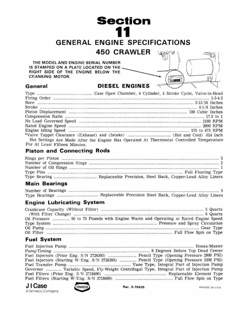
Section 11 GENERAL ENGINE SPECIFICATIONS 450 CRAWLER ~. I THE MODEl AND ENGINE SERIAL NUMBER 0 1 ) IS STAMPED ON A PLATE LOCATED ON THE _______ _ RIGHT SIDE OF THE EN GINE BELOW THE _____ - -'l-' C~A NKING MOTOR . =~[{;~H~?JI=",==, ~I J Ge neral DIESEL ENGINES "i .~ Type .... .. .. ........................ ..... .... Case Open Chamber, 4 Cylinder, 4 Stroke Cycle, Valv e- in-Hea d Firing Order ............................................................ .. ....... ................................................... 1- 3-4-2 Bore .... ................................. ................. ................. .. ....... ............... ................ .. ....... 3· 13/ 16 Inches Stroke ................................................................................. .................... .. .................. 4·]/8 Inches P iston Displacement .............. .. ......................... ................................ .................. 1 88 Cubic Inches Compres sion Ratio ........... ........................ ................ ............ ........... ................................. 17.5 to 1 No Load Governed Speed .......... ................ ......................... ..................... .. .................. .. 2180 RPM Rated Engine Speed ...................................................................................................... 2000 RPM Engine Idling Speed ....... .. ......................... ........ ...................... ......... .................... 575 to 675 RPM · Valve Tappet Clearance (E xhaus t) and (Intake) ................................. (Hot and COld ) . 014 I nch Hot Settings Are Made After the Engine Has Operated At Thermosta t Controlled Temperature For At Least Fifteen Minutes. Piston and Connecting Rods Rings per Piston ..................... .. ... ......................................................... ........................... ...... ..... 3 Number of Compression Rings ............................... .......... ......................... ........................ .......... 2 Number of Oil Rings .......... ...................................................................... ................................ .. . 1 Type Pins .......................... ..................... ................................. .............. .......... Full Floating Type Type Bearing .................. ............... Re placeable Precis ion, Steel Bac k, Co pper· Lead Alloy Liners Main Bearings Number of Bearings .......................... ................ .......... .............. ............. ..................................... 5 Type Bearings ................................ Replaceable Preci sion Steel Back , Copper·Lead Alloy Liners En gine Lubricatin g System Crankcase Ca pacity (Without Filt er) ......... ................... ................ .......... ......................... 5 Quarts (With Filt er Change) ...... .. ................. .. .. ................................................................. ...... 6 Quarts 011 Pressure ............. 50 to 70 Pounds wi th Engine Warm and Operating at Rated Engine Speed Type System ........................................................... . ....... . .. .......... Pressu re a nd Spray Circul ation 011 Pump ........................ .. .................................. ...................... ..... ............................... Gear Type Oil Filter ................................................................... .............................. Full Flow Spin on T ype Fuel System Fuel Injection Pump ............................................................................................... Roosa·Mas ter Pump Timing ........................................ .. ................................ 8 Degrees Before Top Dead Cenler Fuel Injectors ( Prior Eng. SIN 2726393) " .................... Pencil Type (Opening Press ure 2800 PSI ) Fuel Inj ectors (St arti ng Wi Eng. SIN 2726393 ) ............. Pen c il Type (Opening Pressure 3200 PSI) Fuel Tra ns fer Pump .. .... .. ............ ........... ................. Vane Type, In tegra l Part of Injection Pu mp Governor ............ Variab le Speed, Fly·Welght Cen tr if ugal Type, In tegral Part of Inj ection Pu mp Fuel Filters (Pr ior Eng . SIN 2718490) ................................. .. ............. Replaceable Eleme nt Type F uel Fil ters (Starti ng W/ Eng . SIN 2718490) ........................................ Fu ll Flow Spin on Type J I Case e Rae. 9 · 764 35 PRI~TEO I~ USA A Ten neco Co mp any
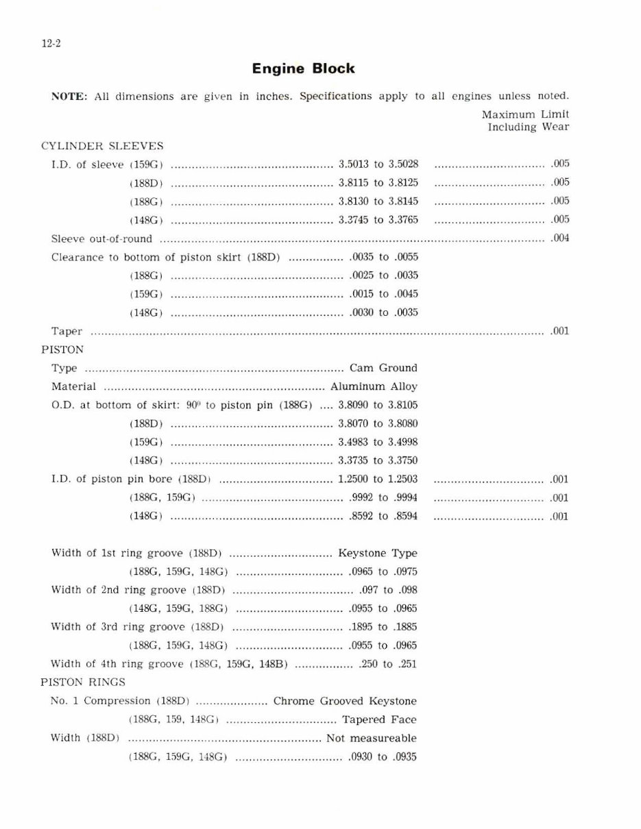
12-2 Engine Block NOTE: All dimensions are given in inche s. Specifications apply to all engines unless noted. C YLINDER S LEEVES J.D. of sleeve (159C ) (1880 I (l88C1 (l48G I ......... ........ . ............. .. ..... .. 3.5013 to 3.5028 ...... .. ................. ......... .. .. ....... 3.8115 to 3.8125 .. .. ............ ... ............ ......... 3.81 30 to 3.8145 .... ................. .. .. .. ......... 3.3745 to 3.3765 Maximum Lim it ln cluding Wear .005 Sleeve out -o f· round ......... .... ... ... . .. ..... .. ......... .. ..... ....... .................... ................. ........ ...... .. .... . .005 .005 .005 .004 Cleara nce to botlom of pi ston s kirt (188D) ................ . 0035 to .0055 (l88GI .. ... ... ...... . ................................... 0025 to .0035 (159C ) (!48GI .0015 to .0045 .0030 to .0035 Tape r PI STON .. . .... ........ ....... ............. ....... ... .. ................ ......................... .. .. ..... . 001 Type ... ......................................... .. .......... .. .............. .. Cam Groun d Mate ria l . .. ... ... ............ . .......... . ................... ........... Al um inum Alloy G.D. at b ottom of s kirt : 90!! to piston pin (l88G ) . .. . 3.8090 to 3.8105 (1 88 01 . .. ......... .. .. ....................... 3.8070 to 3.8080 (!59G I ....... ... ........ ........ . ............ . ...... 3.4983 to 3. 499 8 (H SG I ......... ..... ......... ........... ............. 3.3735 to 3.3750 l. D. of piston pin b ore (18801 ................................. 1. 2500 to 1. 2503 (188C . 15SGI ... ..... .. ...... .. ....................... 9992 to .9994 (148G I . . ......... . ...................................... 859 2 to .8594 Wi dt h of 1st ring groove (lS!:!D) ..... ... _ .... . ................ Key stone Type (18SG . 159G. " 8GI ................................ 0965 to .0975 Width of 2nd ring gr oove ll88D) ........... .. ....................... 09 7 to .098 ( 148G , l 59G , J88G) . .. ......... .. .... .. .... ...... 0955 to .0965 Widt h of 3rd ring groov e (188 0) ................... . ............. 1895 to .1885 (l 88G. 159G, 148G) ..................... ........... 0955 to .0965 Width of 4th ring groove (l 88G, 159G. 148B ) ......... . .. . ..... 250 to .251 PI STON RINGS No .1 Comp r ess ion (188D) ............ .. .. Ch rome Grooved Key sto ne (l 88G. 1 59 . 1 -l 8G) ..... ................ ........... Tapered F ace Width (188D ) ............ ... .. ....... .. ............. . ........ .. ..... Not meas ureable (l88G. !S9G. "8G ) .... ..................... . 0930 to .0935 .OO! .001 .U01
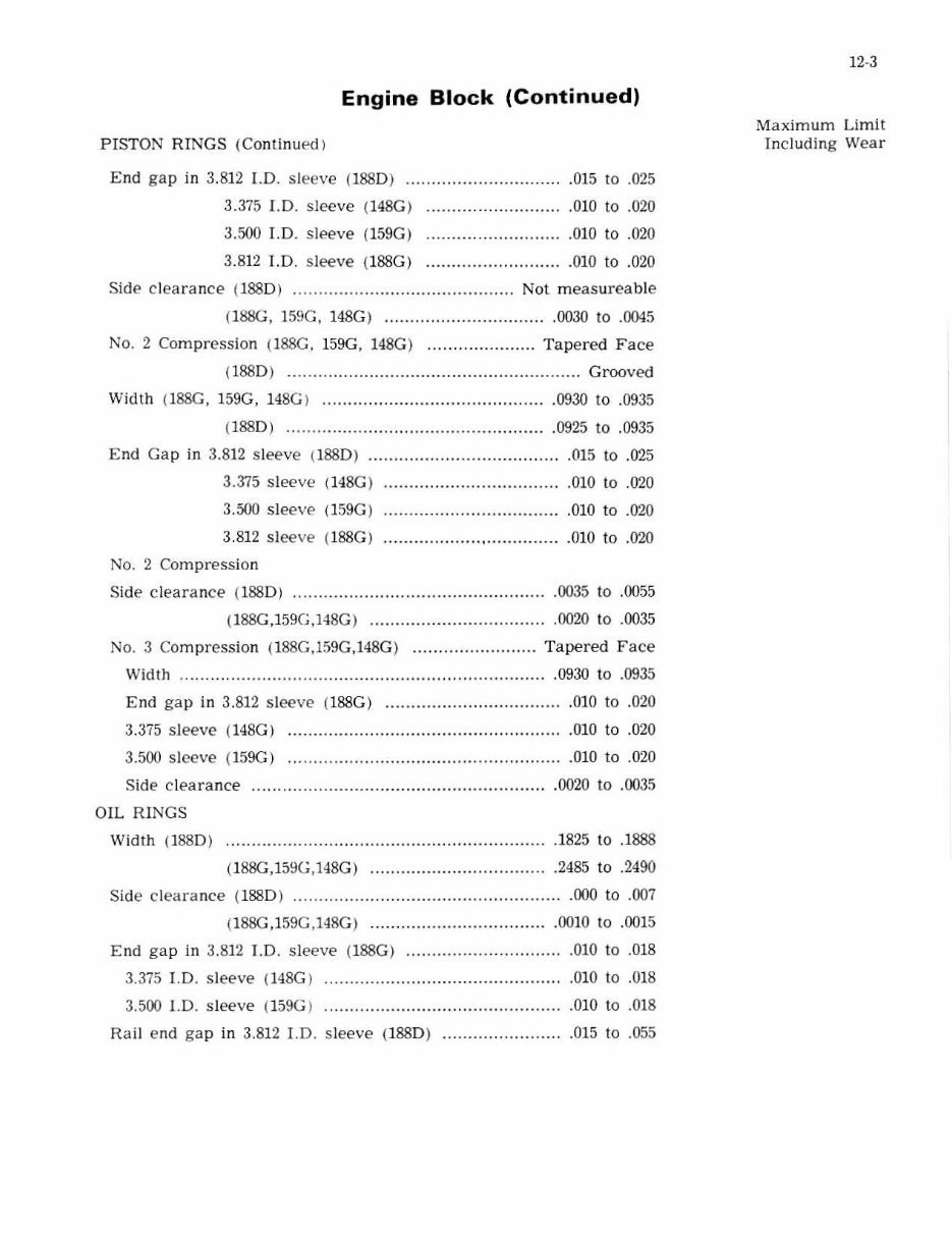
Engine Block (Continued) P ISTON RINGS (Continued) End gap in 3. 812 LD. slee ve (1 880) ... .. ....... ............ ... ... 015 to .025 3.375 I.D. sleeve ( H8G ) 3.500 J.D. sl eeve (159G) 3.812 T. D. sleeve (ISSG) .010 to .020 .010 to .020 .010 to .020 Side clearance (1880) ....................... . ............. ...... Not meas ureab Je (188G. 159G. H SG ) ................................ 0030 to .0045 No.2 Compr ession (l88G, 159G , 148G) ............. __ ...... T apered Face (188D) .... . .................................................... Grooved Width (188G . 159G. 148G ) .. ....... .. .. ............................ ... 0930 to .0935 ( l88D ) ..... .............................................. 0925 to .0935 End Gap in 3.812 sleeve (l88D) ........................ .............. 015 to .025 3.315 s l eeve (H8G ) ........ ...... . .................... 010 to .020 3.500 s l eeve (159G ) 3 .812 slee ve (l88G) No. 2 Compression Side clearance (1880 ) .010 to .020 ................... , ............... 010 to .020 .0035 to .0055 (I88G.159G.14SG) ................................... 0020 to .0035 No.3 Compression (188G.l59G.148G ) ........................ T ape r ed Face \Vidth .......... ...... ............. .. . ...... . ................................. 0930 to .0935 End gap in 3.812 s l eeve (l88G ) ................................... 010 to .020 3.375 sleeve (14SG) ...................................................... 010 to .020 3.500 sleeve ( 159G) .... . ................................................. 010 to .020 Si de c learance ....................... . ...... . .......................... 0020 to .0035 OIL RINGS \Vidt.h (l88D) .......... ...... ........ .... ........... .... . ........ . .......... 1825 to .1888 (188G,159G.148G) .. . ............ . ........... ........ 2485 to .2490 Side cleara nce (l 88D ) ... ..... ............................................. 000 to .007 (188G.159G .148G) ...... ............................. 0010 to .0015 End gap in 3.812 J.D. sleeve ( l88G ) ................. ... .. ......... 010 to .018 3.375 I.D. s leeve (H8G ) .010 to .018 3.500 1.0. sleeve (159G ) ..... .............. . ........................... 01 0 to .018 Rail e nd gap in 3.812 J.D. s leeve (188D) ........................ 015 to .055 12·3 Maximum Limit Including Wear
],·4 Engine Block (Continued) PISTON P]N Type ......................... ...... ................. .... ......... ... ........ Fu ll F loating 0.0. of pin (lAAD) ............... ..... . ............................ 1.2497 to 1.2498 1l88G , 109G ) .. . ..... .. . ,.,,"""""" ,999] to .9992 1148G ) ... "" . .... ". ,,"""""""" .8092 10 .8593 Fit in pi ston (188D ) (lS8G, 159G ) 1l48G ) "" F it in rod bu shing (1880 ) ................... ...... .. . (188G.159G,148G ) .. . ............. . ......... . CON:-.JECTTi\C HOD ,0002 to ,000 6 .0 000 to .0003 . 0000 to .(01)2 .0002 to .0006 .0003 to ,0006 Bushing ............ ......... ........... . . ......... .. Replaceable Bronze Bushing I.D . inst a lled {reamed to size) ( 188G,159G) . ...... .. . ......... ... .. ..... .. ........... 9995 to .999 7 1 188D ) .. ..... .......... ... ................... 1. 2502 to 1.2504 1l48G ) ................. .. ....................... 8596 to .8598 Bushing out·ot-round ............... ...... ................. .......... ..... .. ....... ........ .. ......... . Bearin g Liners ....... .......... .. .... ....... .......... ................... Repla ce able B earing line r width ............. .. . ............................. 1.] 20 to 1.130 Rod width at cra nk cnd ...... . . " " , .......... " " .. . ... 1.3035 to 1.3055 Journal J.D. without bearin g liners .... .. .. ......... ........ 2.1870 to 2.1875 Bearing oil c leara nce ... .... ...... .................................... 0010 to .0035 Under size bcarings for serv ice ....... ..... ............... .. .002,. 010,.020, .030 Side clearance .................. . .. .............. .......................... 0 05 to .011 Cap bolts .... ... ... .. .. .................... ...... ........... ......... Self locking type CRA:"J I{ SHA FT Type ........... .......................... .......... .. ...... ............ ........ ..... Balanced Main bearin g liners ..... .. ........ ........................... .... ....... Replacea ble End play, center main bearing cap .... ..... .......... . Thrust space r s td. thickness .001 to .006 ,092 to ,098 ConneCT in g rod journal std. 0. 0 . .................... ........ . 2.0605 to 2.0615 Grind to .010" 0.0 . undersize .. .... .... . .. ... .. ...... 2.0505 to 2.0515 .020" 0. 0. undersize .030" 0. 0. un de rsize 2.0405 to 2.0415 2. 030 5 to 2.0315 Maximum Limit ln c ludin g Wear .00] .001 ... " ..... . " ,001 .. ............ ,0010 .006 Co nnecting ro cl journal m aximu m taper ........ .. ..... .......... ............... ..................... ... .... ... .... . ,002
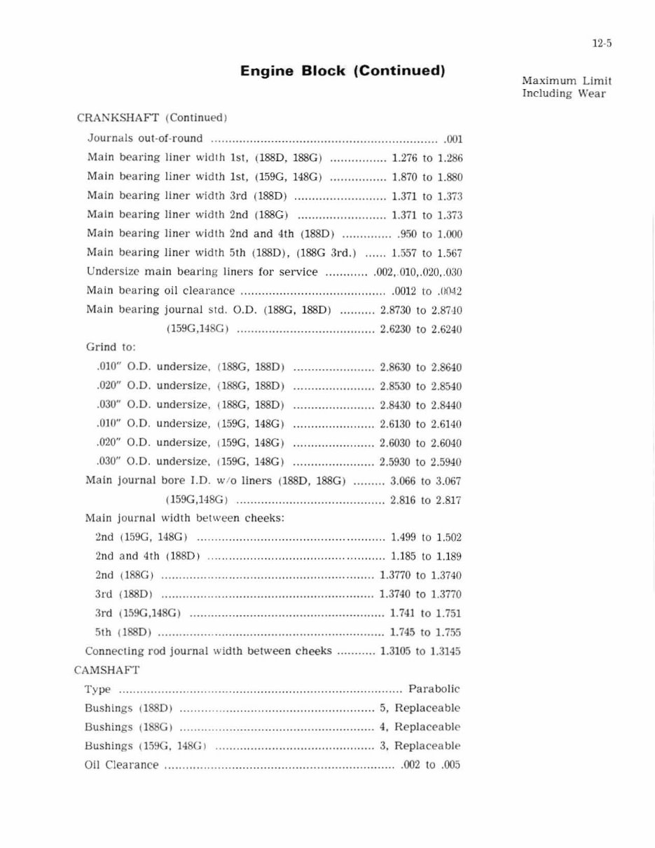
Engine Block (Continued) CRAN KSHAFT (ContinuedJ Journal s out-oC-round .............. .................... __ .. __ ........................ . (Xn Main bearing liner wid th 1st, (I 88D , 188G) .............. __ 1.276 to 1.286 Main bearing liner width 1st, ( 159G, 148G) ............. __ . 1.870 to 1.880 Main bear in g lin er width 3rd (1880) .......................... 1.3il to 1. 373 Main bearing liner width 2nd (l 88G) ......................... 1.371 to 1.373 Main bearing liner width 2nd a nd 4th (1880) .... _____ ..... . 950 to 1.000 Main bearing liner width 5th (1880), (l 88C 3rd.l ...... 1.557 to 1.567 U nd ersize ma in bearing liners for service ............ . 002, .010,.020 .. 030 Main bearing o il clearance ......................................... . 0012 to .0042 Mai n bearing journal S Id. 0 .0 . (lSSG, 1880) .......... 2.8730 to 2.87 · jO (159G ,148G ) ......... .............................. 2.6230 10 2.6240 Grind to: .010" 0.0. undersi ze.. .020" 0.0. undersize, .030" 0.0. und ersi ze , .010" 0.0. undersize, .020" 0.0. und er size, .030" 0.0. undersize, (I88G, 1880 ) (I88G, 1880) !l88G, 1880) (l59G, 148G) 1159G, 148G) (159G. 148G) .. ..................... 2.8630 to 2.8&10 ....................... 2.8530 10 2.8540 ....................... 2.8430 10 2.8440 ......... .............. 2.6130 10 2.6140 . ......... ............. 2.6030 10 2.6040 ....................... 2.5930 to 2.59<1 0 Main journal bore 1.0 . w/o liners (1880, 188G) ......... 3.066 10 3.067 (159G,148G) ............................ . ............ 2.816 1 02.817 Main journal width between c heeks: 2nd (159G, 148G) ................................................. 1.499 10 1.502 2nd and 4Th (lB8D) .. .............. ................... ..... ... U85 10 U 89 2nd (188G) ....... . ................................... 1.3770 to 1.3740 3rd (1880) ....... .................................................... 1.3740 to ].3770 3rd (159G,148G) ....................................................... 1.741 to 1.751 5th (1880) ............... . .............. ..... ............................. 1.745 101.755 Connecting rod journal wid th bel wee n cheeks ........... 1. 3105 to 1. 3145 CAMSHM -r Type ................................................................................ Parabolic Bushings (I 88D) ............. .......................................... 5, Replaceable Bushings (1SSG) ...... .... ........ ..................................... 4, Replaceable Bushings (l59G . 148G ) .. ................ ........................... 3, Repla cea bl e Oil Clearance ................................................................. . 002 to .005 12·5 Ma ximum Limit Including Wear
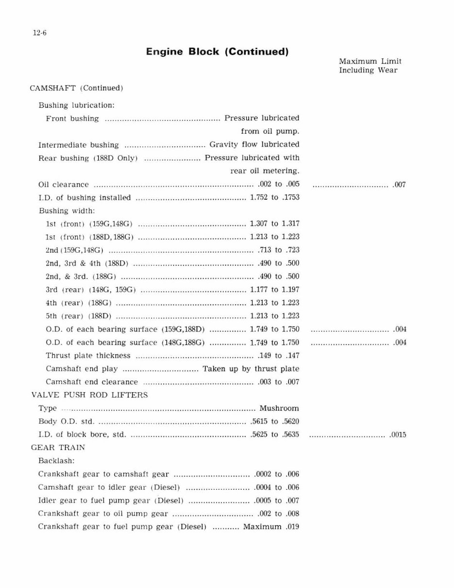
12-6 En gine Block (Continued) CAMSHAFT (Con tinued ) Bushing lubricat ion: Front bushing ............... .. ..... .. ........ ............. . Pres s ure lubricated fr om oil pump . I ntermediate bushing ............ .. . .................. Gravity flow lubr ica ted Rear bushing (1880 Only) ....................... Press ure l ubricated with rear oil metering. Oi l clearance ....... ........ .. .. ...... ..... ....... ....... ..................... 002 to .005 LD. of bushing installed ... . .. ....... ..... ............... ........... 1.752 to .1753 Bushing width: lSI (fronO (159G,148G ) 1 .307 to 1. 317 lSI ( front) (1880, 188G) .......... ... ................. ............. 1.213 to 1.223 ~nd (1 59G, 148G ) .. ......... ....... . ............... ........ ... ........ .... . 713 to .723 2nd, 3rd & 4th (1 88 0) .... .. .. ........... . ........... ............ .. . .490 to .500 2nd, & 3r d. ( l88G) ........... ......................................... .490 to .500 3rd (rear) 1 148G, 159G) ............. ...... ........................ 1.177 to 1.197 4th (re ar ) (188G ) ............. .. .................................. ... . 1.213 to 1.223 5th (re ar ) (188 0) ..... .. . .... ............................... . ......... 1.213 to 1. 223 0.0 . of each bearing surface (159G,188D) 0.0. of e ach bearing surfac e ( 148G ,188G) 1. 749 to 1.750 1.749 to 1.750 Thrust plale thic kne ss ... ... ................................ ........ ... 149 to .147 Cam s haft end play .. ............ . ................ Ta ke n up by thrust pla te Camshaft cnd clearance ..... ............ ....... ................. .. ... 003 to .007 VALVE PUS H ROD LIFTER S Type' .... ............. .. ...... ...... .......... ......... .... ..... .. ........ Mushroom Body 0.0 . std .... . .. .... .. ........ ..... ................................. . 1.0. of block bore, std. GEAR TRAIN Backlash: .5615 to .5620 .5625 to .56.15 Cranksh<'lfl g ear to camshaft ge ar ...... .. ............... .... ..... 0002 to .006 Camshaft gear to Idler gear ( Diesel) ................. . ......... 0004 to .006 Idler gear to fuel pump ge ar (Diesel) .......................... 0005 to .007 Crankshaft gear to oil pump gea r .. ......... ........... ........ .. .002 to .008 Crank s haft g ear to fuel pump gear (Di esel) ... ........ Maximum .0 ]9 Maximum Limit Including Wear ...... ...................... . ... 007 .004 .004 .......................... ..... . 0015
You're Reading a Preview
What's Included?
Lifetime Access
Fast Download Speeds
Online & Offline Access
Access PDF Contents & Bookmarks
Full Search Facility
Print one or all pages of your manual
$52.99
CASE 450 Crawler Loader Tractor Service Repair Manual
This is the complete service repair manual for the CASE 450 CRAWLER LOADER TRACTOR. It contains comprehensive information about maintaining, assembling, disassembling, and servicing your CASE 450 CRAWLER LOADER TRACTOR.
This manual includes detailed specifications, diagrams, real photo illustrations, and schemes, providing step-by-step operations on repair, servicing, technical maintenance, and troubleshooting procedures for your machine. It offers all the information needed for repairing your machine, enabling you to identify issues and understand how to maintain and repair your machine without the need for professional service.
Trouble Shooting the Transmission/Converter Hydraulic System with a Flowmeter
Transmission/Converter Hydraulic System Diagram, Transmission Removal, Transmission Controls
Torque Converter
Charging Pump
De-clutch Lockout
Drive Shafts
70 - BRAKES
Master Cylinders, Parking Brakes, Adjustments
80 - ELECTRICAL SYSTEM
Wiring Diagrams
Trouble Shooting
Ignition System
Batteries
Starter and Starter Solenoid
Generator and Voltage Regulator
90 - MOUNTED EQUIPMENT
Loader
Dozers
Models 9 & 19 Gearmatic Winches
Ripper
Rollover Protection Structure
Models 26 & 26C Backhoe
Model 32 Backhoe
Model 33 Backhoe
Seat and Tank Assembly
Model Specification: CASE 450 CRAWLER LOADER TRACTOR
Language: English
Total Pages: 643
File Format: PDF
Requirements: Adobe Reader
Specifications: Fully Printable & Bookmarked
Compatible: All Versions of Windows & Mac, APP ISO, iPhone, iPad, Android, etc.
This quality manual is 100% complete and intact, with no missing/corrupt pages/sections. The file is bookmarked and searchable for easy navigation. Detailed illustrations, exploded diagrams, drawings, and photos guide you through every service repair procedure. The manual can be viewed on any computer, zoomed, and printed. It comes in PDF format, compatible with all PC-based Windows operating systems and Mac. It can be saved to your hard drive and burned to CD-ROM. Instant download means there are no shipping costs or waiting for a CD or paper manual to arrive in the mail. You will receive this manual today via instant download on completion of payment via our secure payment processor. We accept all major credit/debit cards and PayPal. You can do the repairs yourself and save money.
Reviews
Q&A
Recently Viewed
5,521,897Happy Clients
2,594,462eManuals
1,120,453Trusted Sellers
15Years in Business
Price:
Actual Price:
CASE 450 Crawler Loader Tractor Service Repair Manual