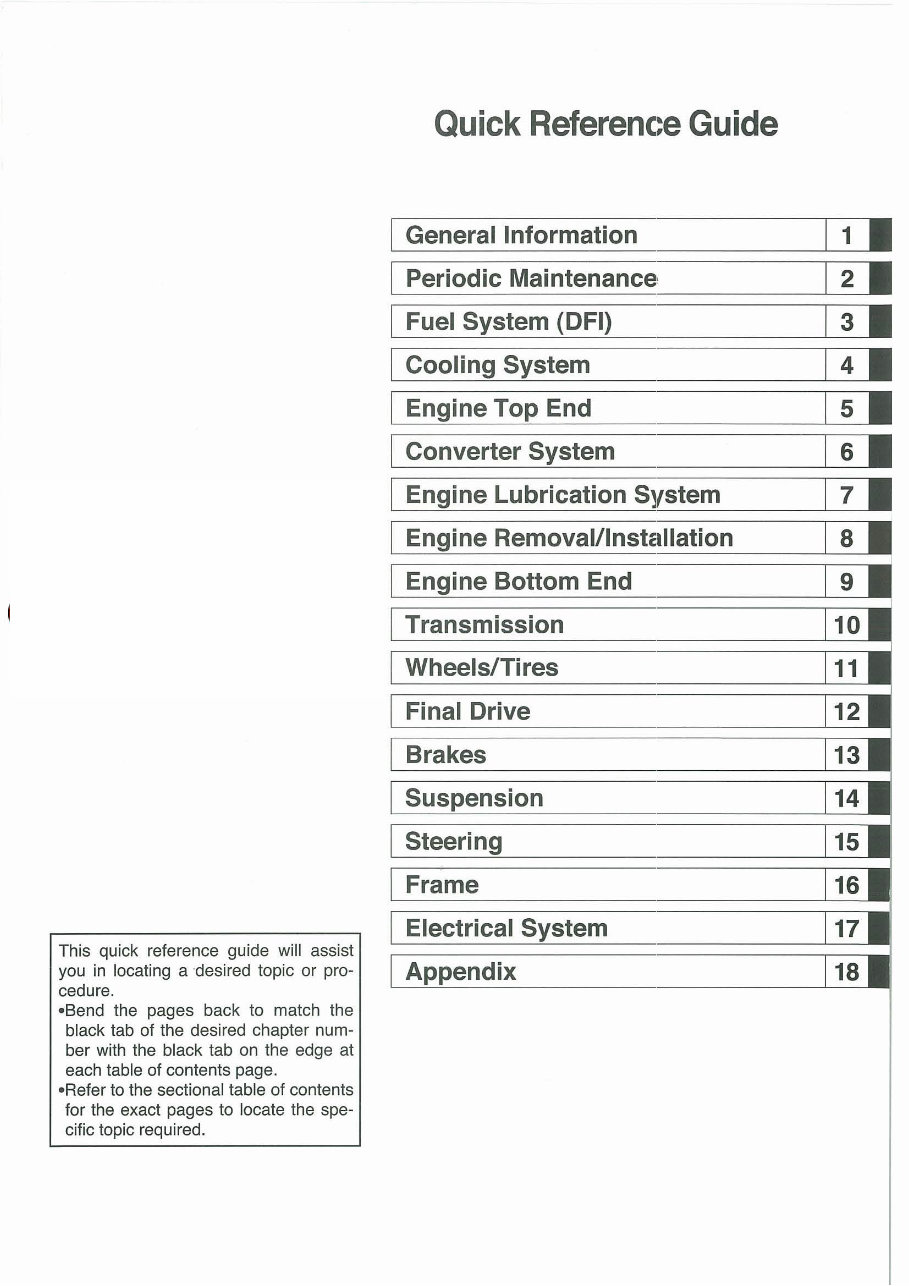
sales@mi com www.midwestmanuals.com This quick reference guide will assist you in locating a desired topic or pro- cedure. -Send the pages back to match the black tab of the desired chapter num- ber with the black tab on the edge at each table of contents page. -Refer to the sectional table of contents for the exact pages to locate the spe- cific topic required. Quick Reference Guide General Information Periodic Maintenance, Fuel System (DFI) Cooling System Engine Top End Converter System Engine Lubrication System ne Removal/Installation ne Bottom End Transmission Wheels/Tires Final Drive on Frame Electrical dix 1 • 2 • 3 • 4 • 5 • 6 • 7 •
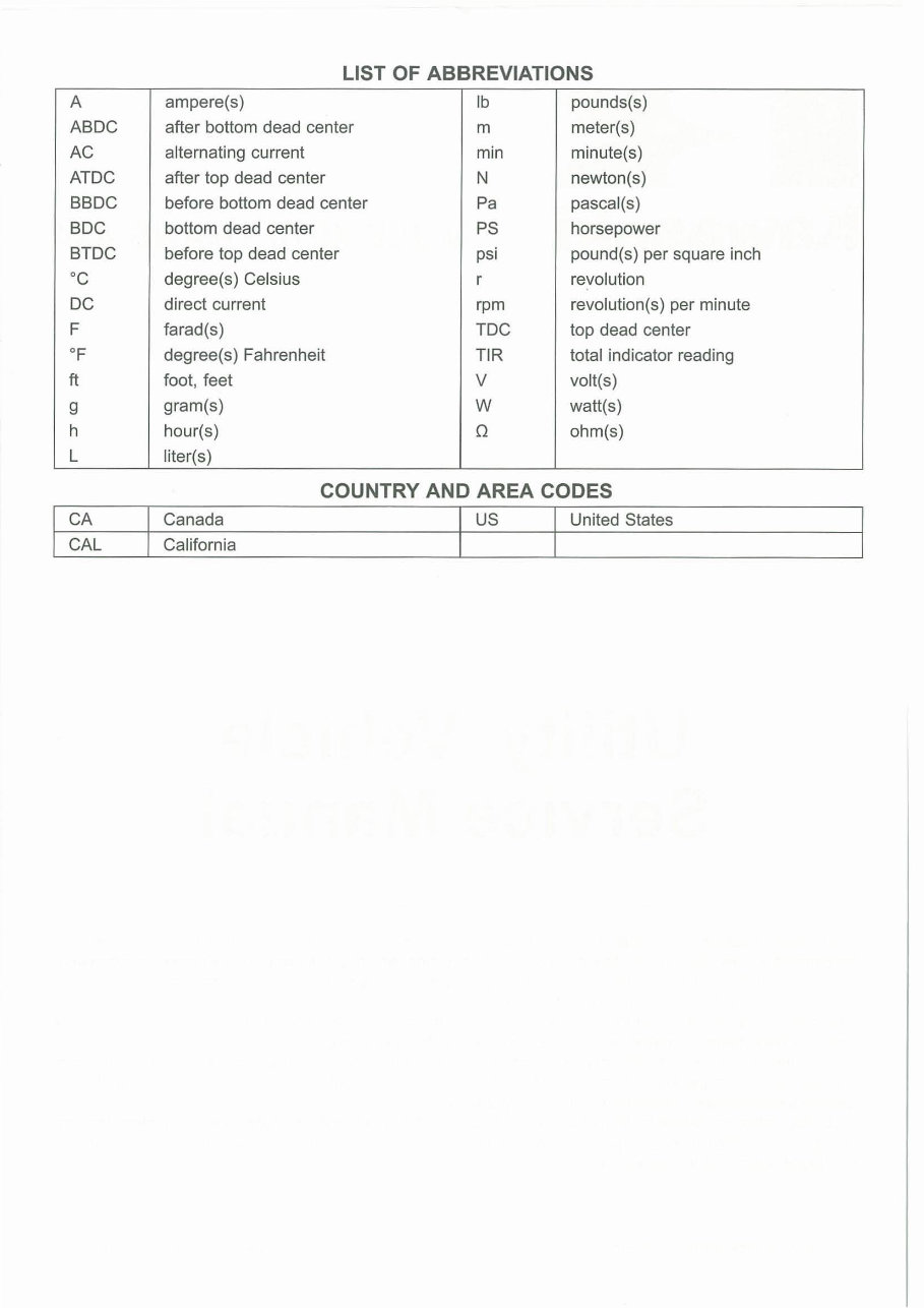
LIST OF ABBREVIATIONS A ampere(s) Ib pounds(s) ABDC after bottom dead center m meter(s) AC alternating current min minute(s) ATOC after top dead center N newton(s) BBDC before bottom dead center Pa pascal(s) BDC bottom dead center PS horsepower BTOC before top dead center psi pound(s) per square inch °C degree(s) Celsius r revolution DC direct current rpm revolution(s) per minute F farad(s) TOC top dead center of degree(s) Fahrenheit TIR total indicator reading ft foot, feet V volt(s) 9 gram(s) W watt(s) h hour(s) Q ohm(s) L liter(s) COUNTRY AND AREA CODES CA Canada US United States CAL California
WE RECOMMEND THAT ALL DEALERS OBSERVE THESE PROVISIONS OF FEDERAL LAW, THE VIOLATION OF WHICH IS PUNISHABLE BY CIVIL PENALTIES NOT EXCEEDING $10000 PER VIOLATION.
PLEASE DO NOT TAMPER WITH NOISE CONTROL SYSTEM (US Model only) To minimize the noise emissions from this product, Kawasaki has equipped it with effective inlet and exhaust silencing systems. They are designed to give optimum performance while maintaining a low noise level. Please do not remove these systems, or alter them in any way which results in an increase in noise level.
Foreword This manual is designed primarily for use by trained mechanics in a properly equipped shop. However, it contains enough detail and basic in- formation to make it useful to the owner who de- sires to perform his own basic maintenance and repair work. A basic knowledge of mechanics, the proper use of tools, and workshop proce- dures must be understood in order to carry out maintenance and repair satisfactorily. When- ever the owner has insufficient experience or doubts his ability to do the work, all adjust- ments, maintenance, and repair should be car- ried out only by qualified mechanics. In order to perform the work efficiently and to avoid costly mistakes, read the text, thor- oughly familiarize yourself with the procedures before starting work, and then do the work care- fully in a clean area. Whenever special tools or equipment are specified, do not use makeshift tools or eqUipment. Precision measurements can only be made if the proper instruments are used, and the use of substitute tools may ad- versely affect safe operation. For the duration of the warranty period, we recommend that all repairs and scheduled maintenance be performed in accordance with this service manual. Any owner maintenance or repair procedure not performed in accordance with this manual may void the warranty. To get the longest life out of your vehicle. • Follow the Periodic Maintenance Chart in the Service Manual. • Be alert for problems and non-scheduled maintenance. • Use proper tools and genuine Kawasaki Vehi- cle parts. Special tools, gauges, and testers that are necessary when servicing Kawasaki vehicles are introduced by the Service Man- ual. Genuine parts provided as spare parts are listed in the Parts Catalog. • Follow the procedures in this manual care- fully. Don't take shortcuts. • Remember to keep complete records of main- tenance and repair with dates and any new parts installed . How to Use This Manual In this manual, the product is divided into its major systems and these systems make up the manual's chapters. The Quick Reference Guide shows you all of the product's system and assists in locating their chapters. Each chapter in turn has its own comprehensive Ta- ble of Contents. For example, if you want engine oil informa- tion, use the Quick Reference Guide to locate the Engine Lubrication System chapter. Then, use the Table of Contents on the first page of the chapter to find the Engine Oil section. Whenever you see these WARNING and CAUTION symbols, heed their instructions! Always follow safe operating and maintenance practices. A WARNING This warning symbol identifies special instructions or procedures which, if not correctly followed, could result in per- sonal injury, or loss of life. CAUTION This caution symbol identifies special instructions or procedures which, if not strictly observed, could result in dam- age to or destruction of equipment. This manual contains four more symbols (in addition to WARNING and CAUTION) which will help you distinguish different types of informa- tion. NOTE o This note symbol indicates points of par- ticular interest for more efficient and con- venient operation. • Indicates a procedural step or work to be done. Olndicates a procedural sub-step or how to do the work of the procedural step it follows. It also precedes the text of a NOTE. * Indicates a conditional step or what action to take based on the results of the test or inspec- tion in the procedural step or sub-step it fol- lows. In most chapters an exploded view illustration of the system components follows the Table of Contents. In these illustrations you will find the instructions indicating which parts require spec- ified tightening torque, oil, grease or a locking agent during assembly.
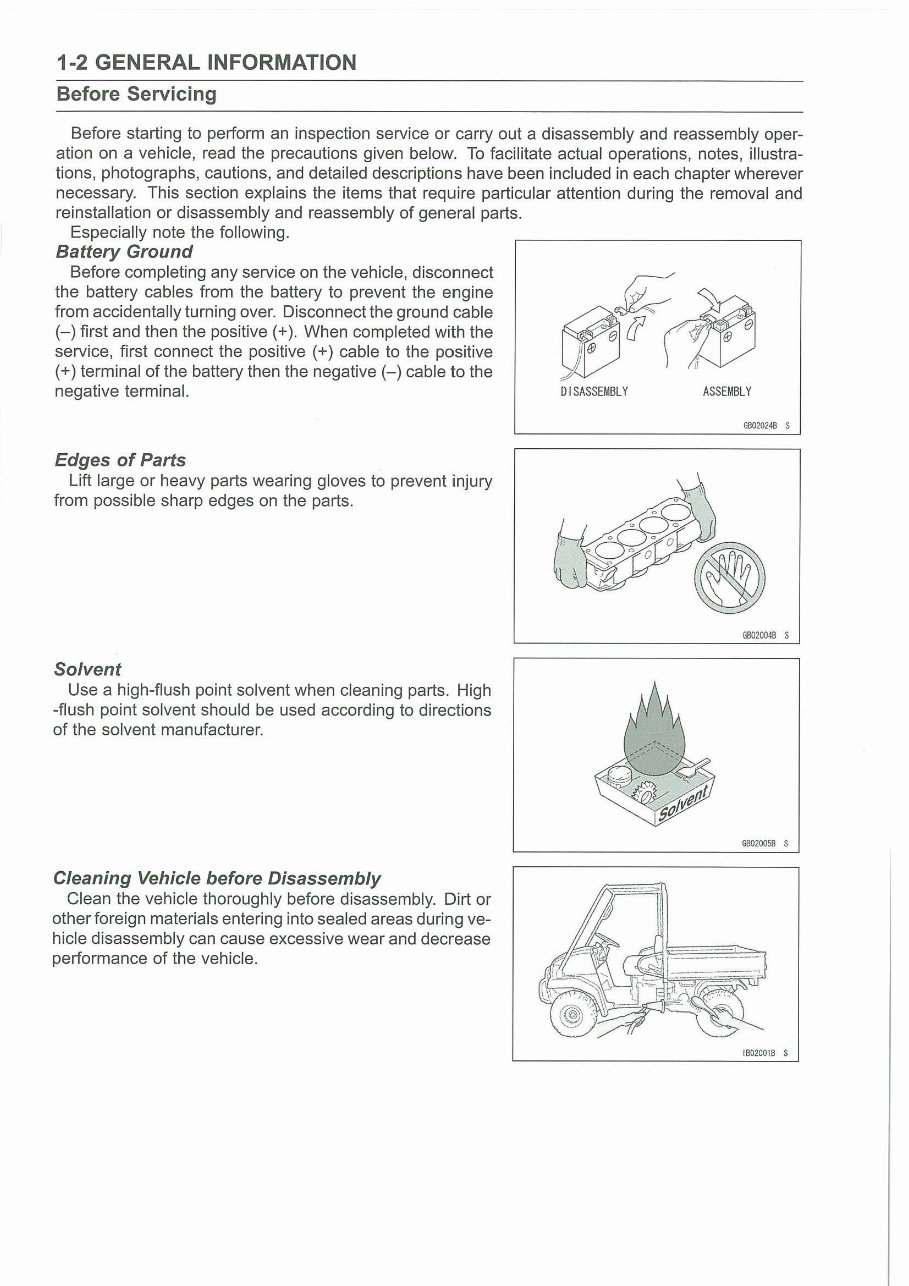
1-2 GENERAL INFORMATION Before Servicing Before starting to perform an inspection service or carry out a disassembly and reassembly oper- ation on a vehicle, read the precautions given below. To facilitate actual operations, notes, illustra- tions, photographs, cautions, and detailed descriptions have been included in each chapter wherever necessary. This section explains the items that require particular attention during the removal and reinstallation or disassembly and reassembly of general parts. Especially note the following. Battery Ground Before completing any service on the vehicle, disconnect the battery cables from the battery to prevent the engine from accidentally turning over. Disconnect the ground cable (-) first and then the positive (+). When completed with the service, first connect the positive (+) cable to the positive (+) terminal of the battery then the negative (-) cable to the negative terminal. Edges of Parts Lift large or heavy parts wearing gloves to prevent injury from possible sharp edges on the parts. Solvent Use a high-flush point solvent when cleaning parts. High -flush point solvent should be used according to directions of the solvent manufacturer. Cleaning Vehicle before Disassembly Clean the vehicle thoroughly before disassembly. Dirt or other foreign materials entering into sealed areas during ve- hicle disassembly can cause excessive wear and decrease performance of the vehicle. DISASSEMBLY ASSEMBLY G8020248 S GB020048 S 00020058 S 18020018 S
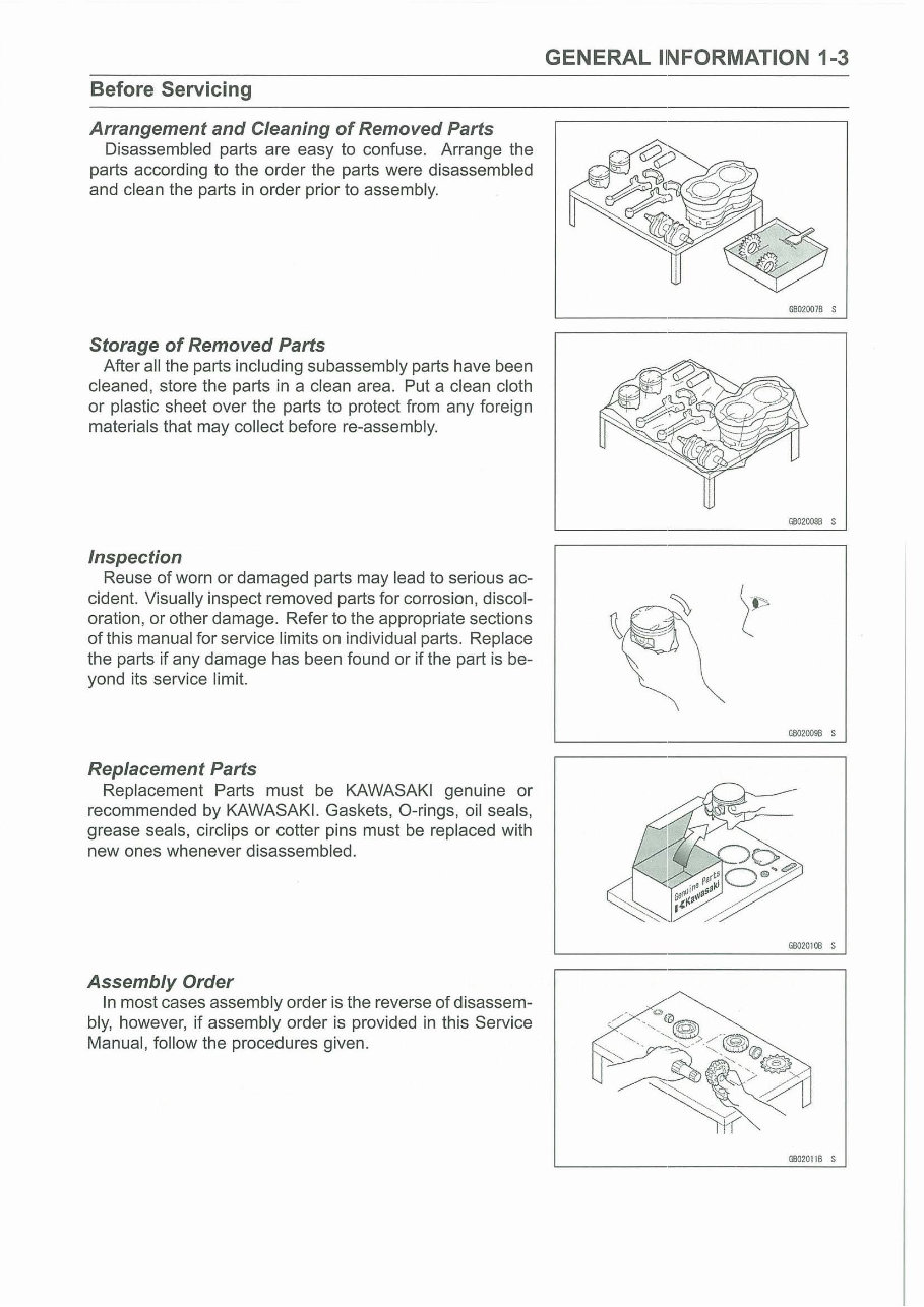
Before Servicing Arrangement and Cleaning of Removed Parts Disassembled parts are easy to confuse. Arrange the parts according to the order the parts were disassembled and clean the parts in order prior to assembly. Storage of Removed Parts After all the parts including subassembly parts have been cleaned, store the parts in a clean area. Put a clean cloth or plastic sheet over the parts to protect from any foreign materials that may collect before re-assembly. Inspection Reuse of worn or damaged parts may lead to serious ac- cident. Visually inspect removed parts for corrosion , discol- oration, or other damage. Refer to the appropriate sections of this manual for service limits on individual parts. Replace the parts if any damage has been found or if the part is be- yond its service limit. Replacement Parts Replacement Parts must be KAWASAKI genuine or recommended by KAWASAKI. Gaskets, O-rings, oil seals, grease seals, circlips or cotter pins must be replaced with new ones whenever disassembled. Assembly Order In most cases assembly order is the reverse of disassem- bly, however, if assembly order is provided in this Service Manual, follow the procedures given. GENERAL liN FORMATION 1-3 G602007B s GBOZOOSB S G80Z009B S G6020100 S G0020116 S
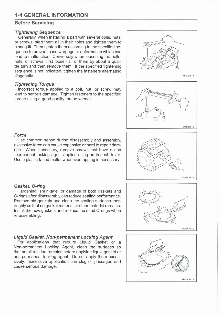
1-4 GENERAL INFORMATION Before Servicing Tightening Sequence Generally, when installing a part with several bolts, nuts, or screws, start them all in their holes and tighten them to a snug fit. Then tighten them according to the specified se- quence to prevent case warpage or deformation which can lead to malfunction. Conversely when loosening the bolts, nuts, or screws, first loosen all of them by about a quar- ter turn and then remove them. If the specified tightening sequence is not indicated, tighten the fasteners alternating diagonally. Tightening Torque Incorrect torque applied to a bolt, nut, or screw may lead to serious damage. Tighten fasteners to the specified torque using a good quality torque wrench. Force Use common sense during disassembly and assembly, excessive force can cause expensive or hard to repair dam- age. When necessary, remove screws that have a non -permanent locking agent applied using an impact driver. Use a plastic-faced mallet whenever tapping is necessary. Gasket, D-ring Hardening, shrinkage, or damage of both gaskets and O-rings after disassembly can reduce sealing performance. Remove old gaskets and clean the sealing surfaces thor- oughly so that no gasket material or other material remains. Install the new gaskets and replace the used O-rings when re-assembling. Liquid Gasket, Non-permanent Locking Agent For applications that require Liquid Gasket or a Non-permanent Locking Agent, clean the surfaces so that no oil residue remains before applying liquid gasket or non-permanent locking agent. Do not apply them exces- sively. Excessive application can clog oil passages and cause serious damage. GB020128 s GB02013B S GB02014B S G8020158 S G602016B S
You're Reading a Preview
What's Included?
Lifetime Access
Fast Download Speeds
Online & Offline Access
Access PDF Contents & Bookmarks
Full Search Facility
Print one or all pages of your manual
$31.99
2009 Kawasaki Mule 4010 KAF620 UTV Service & Repair Manual
Get your hands on the comprehensive repair manual for the 2009 Kawasaki Mule 4010 gasoline UTV. This manual is a valuable resource for professional mechanics and DIY enthusiasts alike, offering in-depth coverage for complete tear-downs and rebuilds, including detailed pictures and part diagrams, torque specifications, maintenance procedures, troubleshooting guides, and much more, spanning across 538 pages.
Featuring clickable chapters and a search function, this manual allows for easy navigation and quick access to the information you need. There are no restrictions on printing or saving/burning to disc, providing you with the flexibility to use the manual as per your convenience.
To explore all available Kawasaki Mule manuals, simply copy and paste the following link into your browser:
http://www.tradebit.com/filesharing.php/search/0/mule/0/1/58622
Reviews
Q&A
Recently Viewed
5,521,897Happy Clients
2,594,462eManuals
1,120,453Trusted Sellers
15Years in Business
Price:
Actual Price:
2009 Kawasaki Mule 4010 KAF620 UTV Service & Repair Manual