Freightliner Cascadia (CA125DC / CA125SLP) Service & Repair Manual
What's Included?
Lifetime Access
Fast Download Speeds
Offline Viewing
Access Contents & Bookmarks
Full Search Facility
Print one or all pages of your manual
Electrical System and Main PDM Overview G02.01 Table of Contents System Overview Terms and Abbreviations .............................................................. 500 Electronic Power Distribution ........................................................... 501 Electrical Power Distribution ............................................................ 502 Powernet Distribution Box ............................................................. 503 Main Ground Junction Block (MGJB), Module 280 ........................................... 504 MEGA Fuse Junction Block (MFJB), Module 285 ............................................ 505 Powertrain PDM, Module 286 .......................................................... 506 Load Disconnect Switch, Module 293 .................................................... 507 Trailer PDM, Module 296 .............................................................. 508 PDM Diagram ...................................................................... 509 Components Component Locations ................................................................ 600 Component Details .................................................................. 601 Troubleshooting Possible Causes .................................................................... 700 Diagnostic Tools Required ............................................................. 701 Diagnosis .......................................................................... 702 PNDB Troubleshooting ................................................................ 703 SAM Cab and SAM Chassis Automatic Resetting Circuit Protection ............................. 704 Specifications SAM Chassis Fuses and Relays ........................................................ 800 SAM Cab Fuses and Relays ........................................................... 801 MFJB Fuses ....................................................................... 802 Powertrain PDM and Trailer PDM Fuses and Relays ......................................... 803 Primary PNDB Fuses and Functions ..................................................... 804 Cascadia Troubleshooting Manual, September 2012
Electrical System and Main PDM Overview G02.01 500 — Terms and Abbreviations Backbone—The main J1939 datalink wiring that lies between the two terminating resistors. It does not include the branch circuits to each ECU or to the diagnostic connector. CAN—Controller Area Network CAN ID—The identifier for a specific message, which also contains the source address of the sending ECU communicating on the J1939 datalink. CGW—Central Gateway Communication Protocol—A set of rules governing communication between electronic devices. Datalink—A collection of wires, connecting system components, through which data is transmitted. Datalink Topology—The arrangement in which the nodes (ECUs) of a datalink are connected to each other. Diagnostic CAN—Datalink that runs from the diagnostic connector to the CGW. Diagnostic Connector—A 9-pin diagnostic connector is used for troubleshooting the electrical system. MFJB—MEGA ® Fuse Junction Block MGJB—Main Ground Junction Block SA—Source Address; indicates numeric assignment for a device that communicates on J1939. SAM—Signal Detect and Actuation Module SAM Cab—Signal Detect and Actuation Module Cab ("SAM Cabin"); this ECU controls mainly cab-related func- tionality. See G02.04 — SAM Cab for more information. SAM Chassis—Signal Detect and Actuation Module Chassis; this ECU controls mainly chassis-related function- ality. See G02.05 — SAM Chassis for more information. 501 — Electronic Power Distribution The multiplexed system contains the following power distribution components: • SAM Cab (relays and fuses), Module 32A • SAM Chassis (relays and fuses), Module 32K The SAM Cab and SAM Chassis are electronic control units (ECUs) that have power distribution components such as fuses and relays on them. Refer to G02.04 — SAM Cab and G02.05 — SAM Chassis for more infor- mation. The SAM Chassis and SAM Cab may use self-resetting circuit protection instead of fuses for some circuits. When the temperature of the SAM is above 170 F (77 C), it is in the tripped state. When it cools off, the circuit will again be energized. See 704 — SAM Cab and SAM Chassis Self-Resetting Circuit Protection. IMPORTANT: Do not change the self-resetting circuit breakers without using the special removal tool, located inside the cover of the SAM device. See Fig. 13. Failure to use the special tool could result in component damage. 502 — Electrical Power Distribution Standard electrical power distribution provides battery power to the electronics system, but it is not controlled by electronics. Cascadia Troubleshooting Manual, September 2012 G02.01/1
G02.01 Electrical System and Main PDM Overview The following modules are part of power distribution: • Main Ground Junction Block (MGJB), Module 280 • MEGA Fuse Junction Block (MFJB), Module 285 • Powertrain PDM, Module 286 • PNDB, Module 33P • Load Disconnect Switch, Module 293 • Trailer PDM, Module 296 503 — Powernet Distribution Box The powernet distribution box (PNDB) distributes and fuses battery power to many of the vehicle loads. An op- tional cab load disconnect switch (CLDS) is available to disconnect selected circuits. The CLDS may be located on the chassis near the battery box or mounted so that it is operated from inside the cab. There is an LED in the CLDS that will illuminate when power is on. The LED will flash when certain faults are detected. Some vehicles have an auxiliary PNDB in addition to the primary PNDB. If the vehicle is equipped with a CLDS, it controls both. An additional LED status indicator is in the CLDS on dual PNDB systems. 504 — Main Ground Junction Block (MGJB), Module 280 The MGJB is a main node for connecting a returning ground to the battery. Many of the ground circuits previ- ously on the starter are now on the MGJB. 505 — MEGA Fuse Junction Block (MFJB), Module 285 The MFJB houses up to 5 MEGA fuses, and provides power to the engine harness, SAM Cab, SAM Chassis, chassis-mounted trailer PDM, and an inverter. The advantage of using an MFJB is that it provides increased robustness in the engine control and cab control electronic systems during cranking. This is because the cab electrical system is fed from the battery through the MFJB, and no longer from the starter. Separate starter cables provide both higher voltage levels and cleaner power during cranking. Additionally, there are improvements in circuit protection, and starter connection integrity (fewer circuits to con- nect at the starter stud). 506 — Powertrain PDM, Module 286 The Powertrain Power Distribution Module (PT-PDM) is dedicated to providing battery and ignition power to the engine (ECM), after treatment device (ATD), transmission (TCU), as well as other powertrain-related circuits. It is mounted in the engine compartment, above the quarter fender on the driver side of the vehicle. 507 — Load Disconnect Switch, Module 293 The load disconnect switch is used to disconnect (or open) the connection between the battery and the MFJB. Turning the load disconnect switch to the off position does not disconnect the batteries from the starter. NOTE: If the engine is running, turning the load disconnect switch to the OFF position will not shut off the engine. The powertrain PDM still gets battery voltage from the emergency power feed on the SAM system. Cascadia Troubleshooting Manual, September 2012 G02.01/2
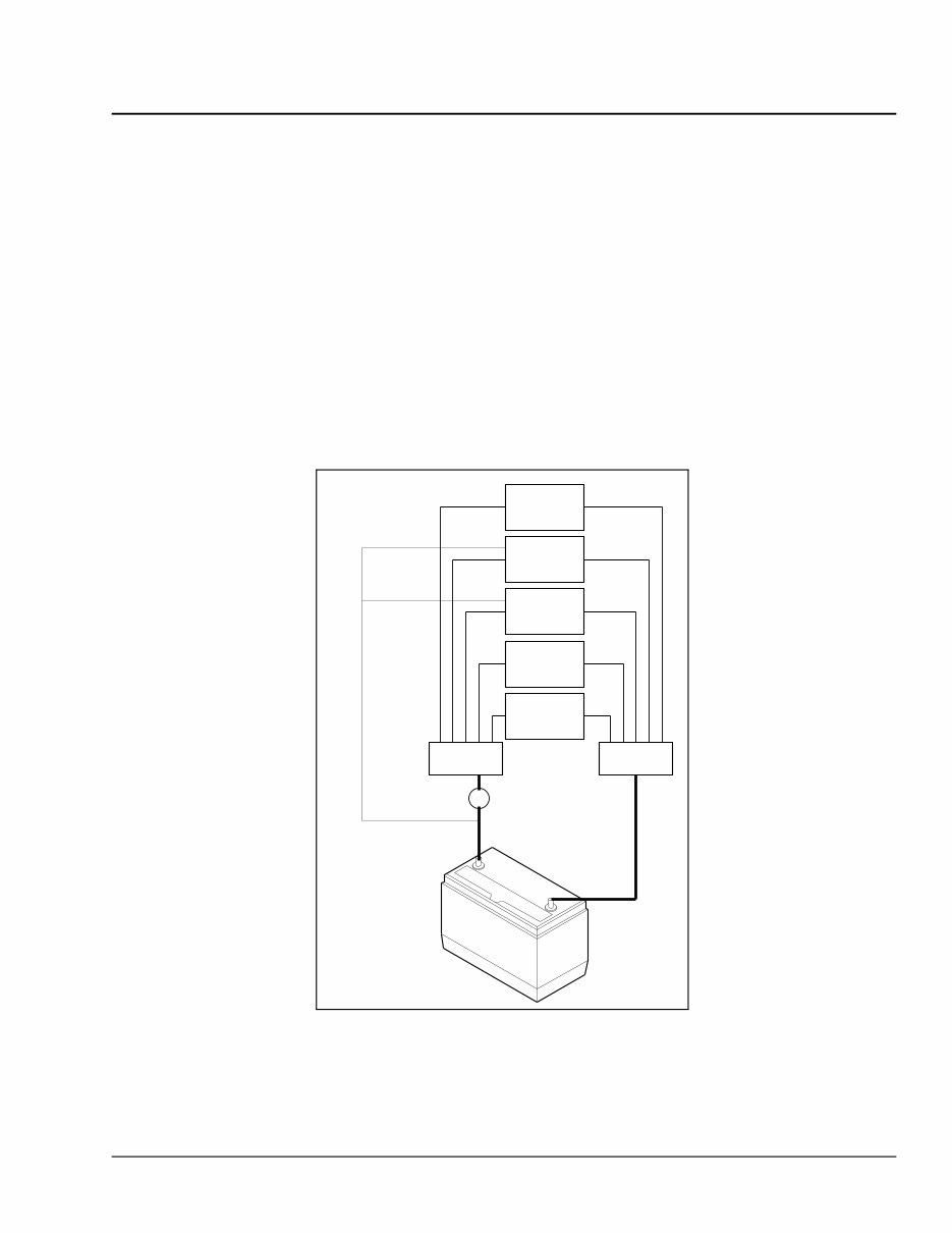
Electrical System and Main PDM Overview G02.01 The load disconnect switch is mounted on one of three locations: • Inside the cab on the left side of the driver’s seat on a left-hand-drive vehicle. • On the battery box. • Outboard-mounted on the left frame rail. 508 — Trailer PDM, Module 296 The trailer PDM is used to supply trailer power to the chassis-mounted trailer receptacles. The SAM Chassis supplies control outputs to the remote trailer PDM. The trailer PDM is powered through the vehicle’s battery sys- tem. The SAM Chassis does not supply battery power to the trailer PDM. See Fig. 1. 509 — PDM Diagram MFJB MGJB Load Disconnect Switch Emergency Power Feed PT-PDM SAM Cab SAM Chassis Trailer PDM Inverter 04/24/2007 f545016 Fig. 1, PDM Diagram Cascadia Troubleshooting Manual, September 2012 G02.01/3
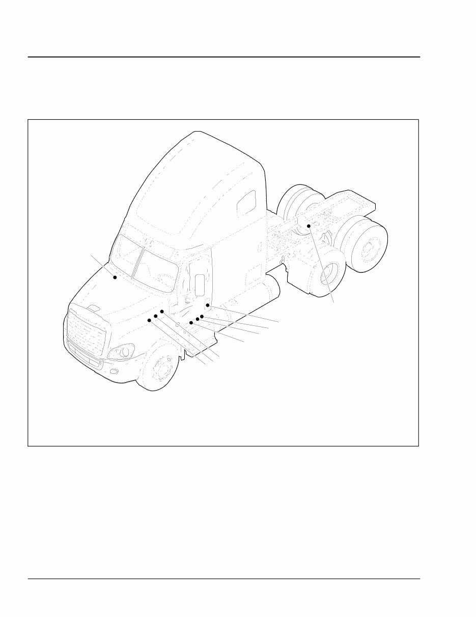
G02.01 Electrical System and Main PDM Overview 600 — Component Locations f001175a 02/27/2012 2 1 4 9 8 6 5 3 7 1. SAM Cab 2. Powertrain PDM (PT-PDM) 3. Powernet Distribution Box (PNDB) 4. SAM Chassis 5. Main Ground Junction Block (MGJB) 6. MEGA Fuse Junction Block (MFJB) 7. Cab Load Disconnect Switch (optional location) 8. Cab Load Disconnect Switch (optional location) 9. Trailer PDM Fig. 2, Component Locations Cascadia Troubleshooting Manual, September 2012 G02.01/4
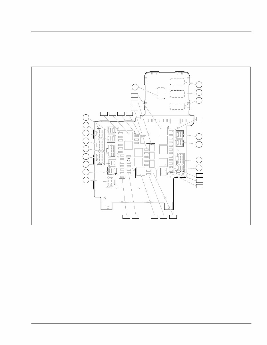
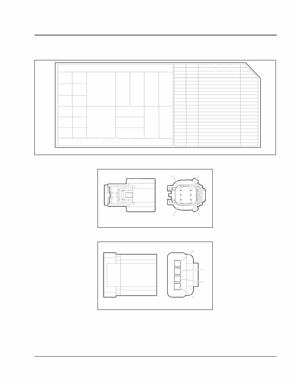
Electrical System and Main PDM Overview G02.01 601 — Component Details f545092 X14 X15 X16 X17 F29 R15 F40 X18 X20 X4 X1 X5 X2 X6 X3 X7 X9 F18 R6 F28 R10 F13 F1 R1 F19 F22 R7 R11 X21 09/19/2007 NOTE: The square labels indicate fuses and relays, and the circular labels indicate connectors. R3 R14 X8 X19 Fig. 3, SAM Cab Fuses and Relays (top) Cascadia Troubleshooting Manual, September 2012 G02.01/5
G02.01 Electrical System and Main PDM Overview 01/25/2007 f544954 Fig. 4, SAM Chassis 05/18/2007 f545054 Fig. 5, Powertrain PDM (EPA07) Cascadia Troubleshooting Manual, September 2012 G02.01/6
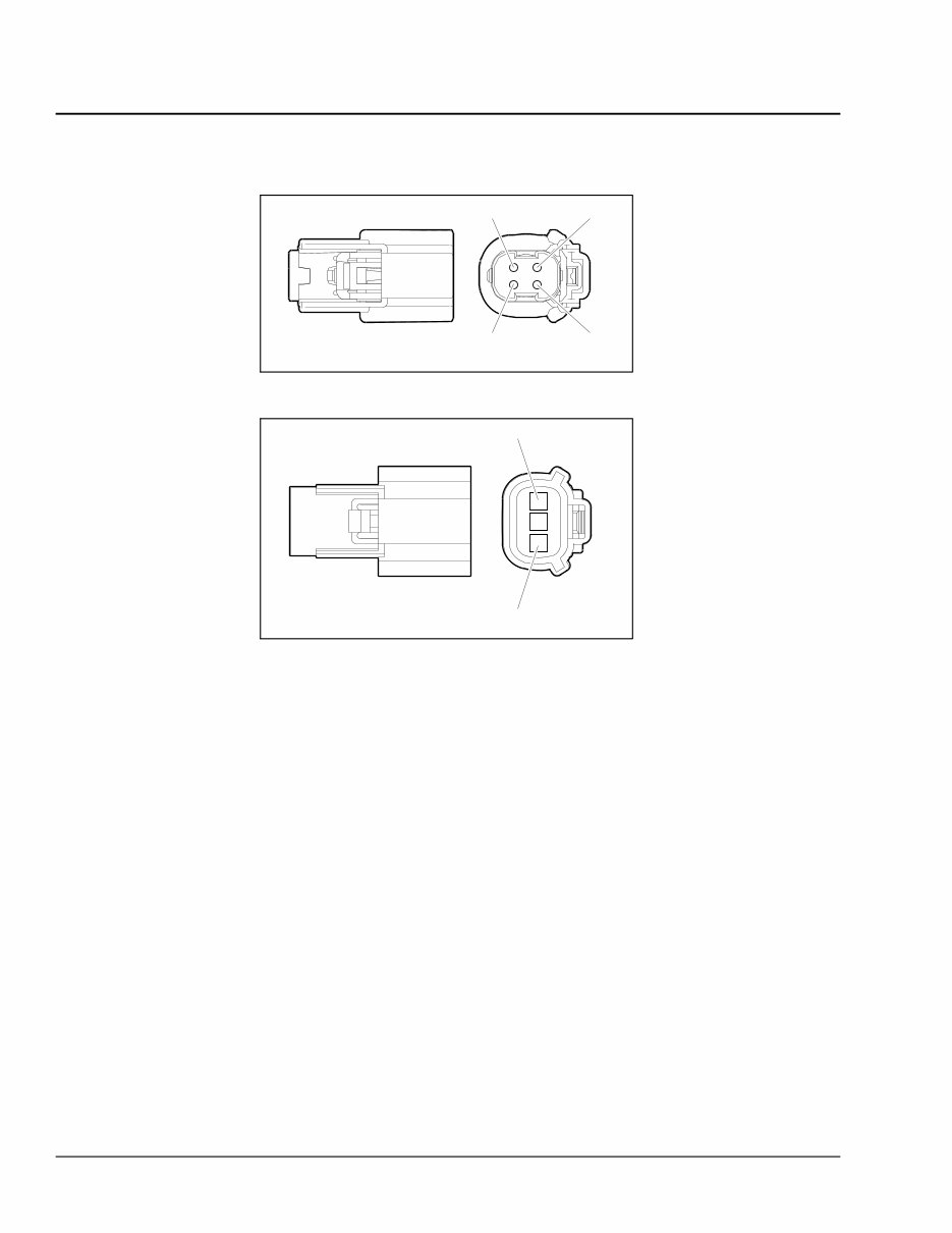
G02.01 Electrical System and Main PDM Overview 11/29/2010 f545708 1 2 3 4 Fig. 9, Wire Insertion View of CLDS Connector X1 11/29/2010 f545709 1 3 Fig. 10, Wire Insertion View of CLDS Connector X2 700 — Possible Causes • Water Intrusion • Voltage Spikes • Short Circuits • Missing Fuse/Relay • Incorrect Fuse Rating 701 — Diagnostic Tools Required • Digital Multimeter 702 — Diagnosis Refer to the schematic in modules 280 and 285 for an overview of the vehicle power distribution system for trou- bleshooting. Use Table 1to cross reference the individual modules for each subsystem. Cascadia Troubleshooting Manual, September 2012 G02.01/8
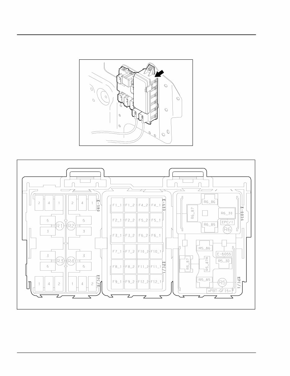
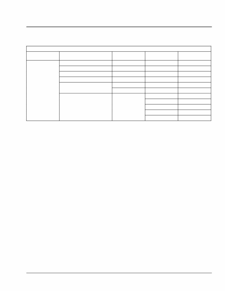
Electrical System and Main PDM Overview G02.01 Power Distribution with Module Numbers Source Battery Node Input/Output Device Secondary Battery Module Starter Bat Terminal Starter Motor — 155 Alternator Bat Terminal Alternator — 125 Grid Heater Heater Element — 12C Jump Start Post — — 295 SAM Cab — 32A Emergency Power Supply SAM Chassis — 32K Powertrain PDM 286 SAM Cab 32A SAM Chassis 32K Trailer PDM 296 Battery Load Disconnect Switch MFJB Inverter 337 Table 1, Power Distribution with Module Numbers 703 — PNDB Troubleshooting Each powernet distribution box (PNDB) on the vehicle provides up to 4 low amperage circuits (30 amp and less), and up to three high amperage circuits through midi fuses. The fuses are located behind a cover on the face of the PNDB. On vehicles equipped with a cab load disconnect switch (CLDS), the high amperage circuits are switched on and off with the CLDS. The low amperage circuits are always live. Vehicles may have one or two PNDBs and both are connected to the same CLDS. When the CLDS is in the on position, an LED on the switch, and another on the PNDB, will be illuminated. When there is an error condition with the PNDB system, the LED on the PNDB and CLDS may flash. A flashing LED indicates an error. An LED that remains on when the switch is off, or no LED when the switch is on, also indi- cates an error condition. To test for open fuses, use conventional troubleshooting methods. The LED’s in the PNDBand switch are not af- fected by open fuses or the circuits they connect. See Fig. 7, Fig. 8, Fig. 9, and Fig. 10 for illustrations of the connectors with pin identification. NOTE: See Table 2 to troubleshoot a switched PNDB system. NOTE: PNDB connector X2 is not part of the switching and control system. See Table 3 for informa- tion on the function of PNDB connector X2. See Fig. 11 for a schematic of the dual PNDB system with the cab load disconnect switch option. Cascadia Troubleshooting Manual, September 2012 G02.01/9
Freightliner Cascadia (CA125DC / CA125SLP) Service & Repair Manual
Variants covered:
CA125DC
CA125SLP
Whether you're a professional mechanic or a DIY enthusiast, this truck repair manual equips you with the necessary troubleshooting and replacement procedures recommended by the manufacturer. It includes step-by-step instructions, clear images, and exploded-view illustrations.
Regular maintenance is essential for the durability of your truck. Over time, certain parts will wear out and require replacement, and this manual provides the manufacturer's recommended troubleshooting charts and replacement procedures to address such issues.
With this comprehensive manual, you can save on repairs, enhance your vehicle's reliability, and minimize visits to the repair shop. It contains all the essential information you need to effectively fix your vehicle.
Featuring step-by-step instructions, exploded-view illustrations, and clear images, this manual eliminates the hassle of searching through numerous pages for specific information. It's easily accessible, searchable, and can be conveniently used on electronic devices such as PCs, Mac computers, smartphones, and tablets.
For those who prefer a physical copy, the manual is also printable. It is available in PDF format and is compatible with various electronic devices. The only requirement is Adobe Reader, which is available for free.
Recently Viewed
5,521,897Happy Clients
2,594,462eManuals
1,120,453Trusted Sellers
15Years in Business
Price:
Actual Price:
Freightliner Cascadia (CA125DC / CA125SLP) Service & Repair Manual