

2024 Yamaha KODIAK 450 EPS Service & Repair Manual
What's Included?
Fast Download Speeds
Online & Offline Access
Access PDF Contents & Bookmarks
Full Search Facility
Print one or all pages of your manual

Repair&ServiceManual
YAMAHA
KODIAK450EPS
KODIAK450
4WD
ServiceManual
-ieee—.~
Fe ur1616-3107
es

eBs20009
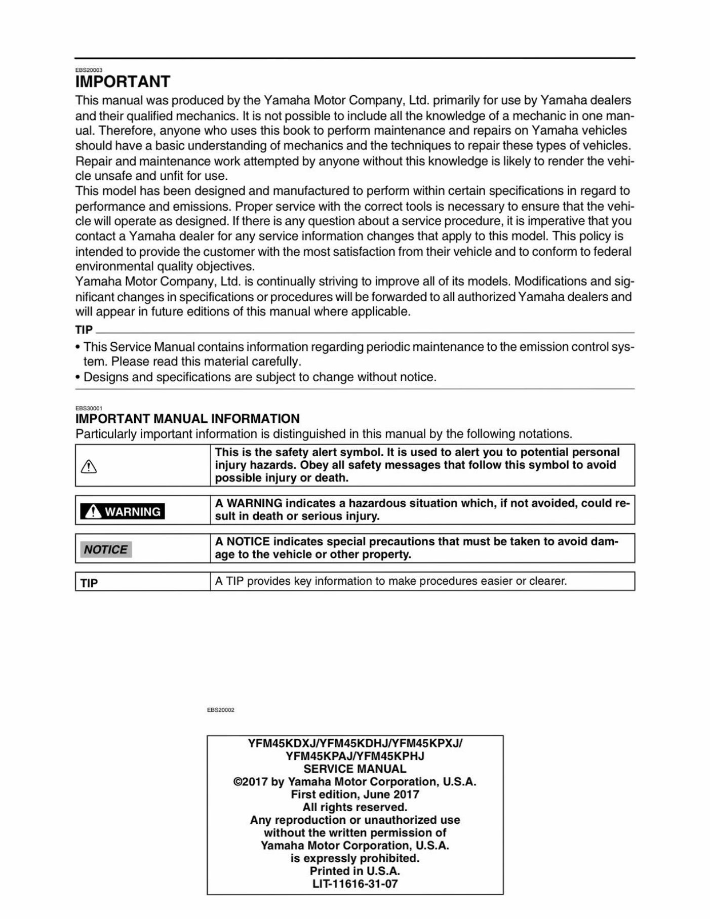
IMPORTANT
ThismanualwasproducedbytheYamahaMotorCompany,Ltd.primarilyforusebyYamahadealers
andtheirqualifiedmechanics.Itisnotpossibletoincludealltheknowledgeofamechanicinoneman-
ual.Therefore,anyonewhousesthisbooktoperformmaintenanceandrepairsonYamahavehicles
shouldhaveabasicunderstandingofmechanicsandthetechniquestorepairthesetypesofvehicles.
Repairandmaintenanceworkattemptedbyanyonewithoutthisknowledgeislikelytorenderthevehi-
cleunsafeandunfitforuse.
Thismodelhasbeendesignedandmanufacturedtoperformwithincertainspecificationsinregardto
performanceandemissions.Properservicewiththecorrecttoolsisnecessarytoensurethatthevehi-
clewilloperateasdesigned.Ifthereisanyquestionaboutaserviceprocedure,itisimperativethatyou
contactaYamahadealerforanyserviceinformationchangesthatapplytothismodel.Thispolicyis
intendedtoprovidethecustomerwiththemostsatisfactionfromtheirvehicleandtoconformtofederal
environmentalqualityobjectives.
YamahaMotorCompany,Ltd.iscontinuallystrivingtoimproveallofitsmodels.Modificationsandsig-
nificantchangesinspecificationsorprocedureswillbeforwardedtoallauthorizedYamahadealersand
willappearinfutureeditionsofthismanualwhereapplicable.
TIP
*ThisServiceManualcontainsinformationregardingperiodicmaintenancetotheemissioncontrolsys-
tem.Pleasereadthismaterialcarefully.
*Designsandspecificationsaresubjecttochangewithoutnotice.
EBS20001
IMPORTANTMANUALINFORMATION
Particularlyimportantinformationisdistinguishedinthismanualbythefollowingnotations.
Thisisthesafetyalertsymbol.Itisusedtoalertyoutopotentialpersonal
ainjuryhazards.Obeyallsafetymessagesthatfollowthissymboltoavoid
possibleinjuryordeath.
AWARNINGindicatesahazardoussituationwhich,ifnotavoided,couldre-
AWARNINGsultindeathorseriousinjury.
ANOTICEindicatesspecialprecautionsthatmustbetakentoavoiddam-
NOTICEagetothevehicleorotherproperty.
TIPATIPprovideskeyinformationtomakeprocedureseasierorclearer.
eas20002
YFM45KDXJ/YFM45KDHJ/YFM45KPXJ/
YFM45KPAJ/YFM45KPHJ
SERVICEMANUAL
©2017byYamahaMotorCorporation,U.S.A.
Firstedition,June2017
Allrightsreserved.
Anyreproductionorunauthorizeduse
withoutthewrittenpermissionof
YamahaMotorCorporation,U.S.A.
isexpresslyprohibited.
PrintedinU.S.A.
LIT-11616-31-07
Easco00e
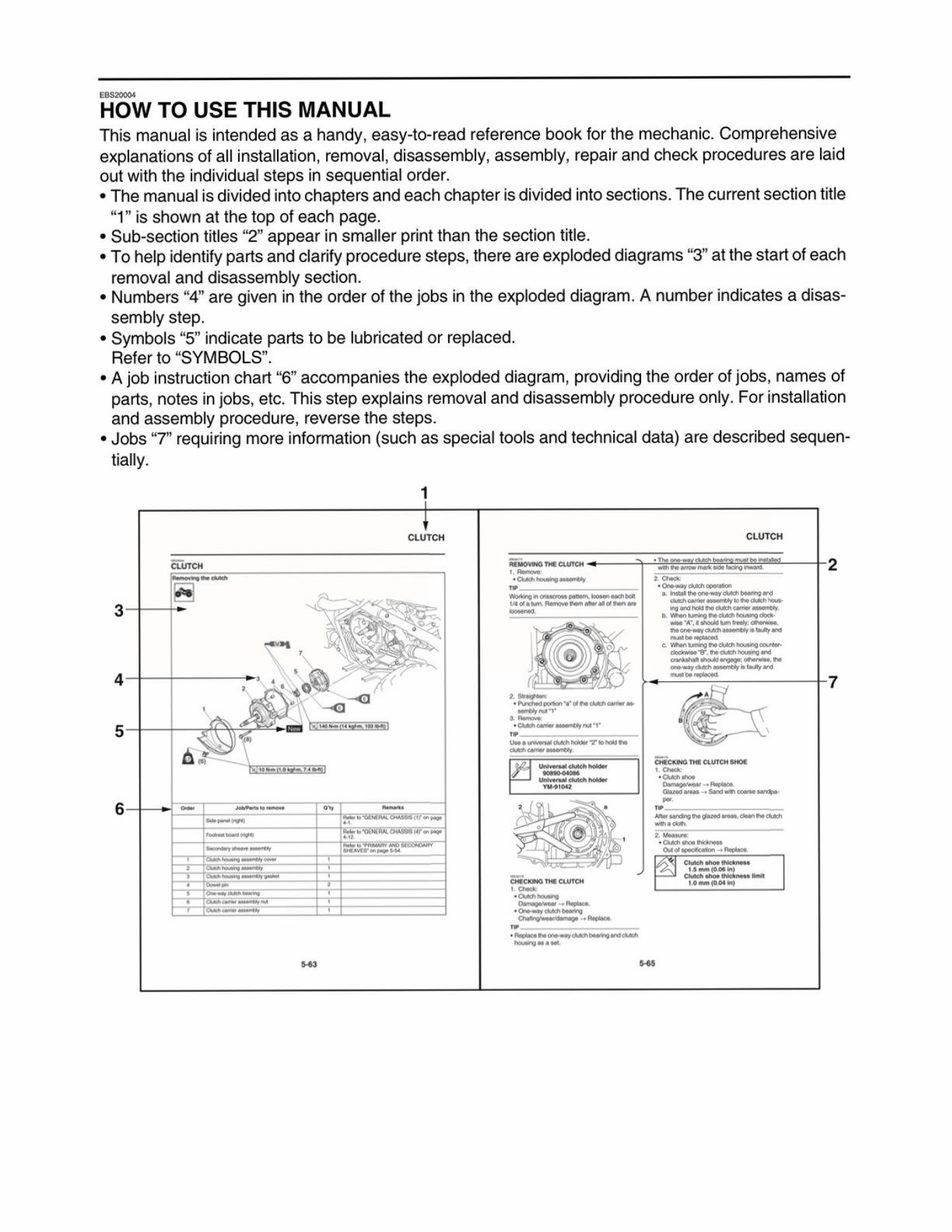
HOWTOUSETHISMANUAL
Thismanualisintendedasahandy,easy-to-readreferencebookforthemechanic.Comprehensive
explanationsofallinstallation,removal,disassembly,assembly,repairandcheckproceduresarelaid
outwiththeindividualstepsinsequentialorder.
*Themanualisdividedintochaptersandeachchapterisdividedintosections.Thecurrentsectiontitle
“1”isshownatthetopofeachpage.
*Sub-sectiontitles“2”appearinsmallerprintthanthesectiontitle.
*Tohelpidentifypartsandclarifyproceduresteps,thereareexplodeddiagrams“3”atthestartofeach
removalanddisassemblysection.
*Numbers“4”aregivenintheorderofthejobsintheexplodeddiagram.Anumberindicatesadisas-
semblystep.
*Symbols“5”indicatepartstobelubricatedorreplaced.
Referto“SYMBOLS”.
«Ajobinstructionchart“6”accompaniestheexplodeddiagram,providingtheorderofjobs,namesof
parts,notesinjobs,etc.Thisstepexplainsremovalanddisassemblyprocedureonly.Forinstallation
andassemblyprocedure,reversethesteps.
*Jobs“7”requiringmoreinformation(suchasspecialtoolsandtechnicaldata)aredescribedsequen-
tially.
<a
CLUTCH
‘enenaryyan
«nanurnheathRouleg
GiigexoaTHECLUTCHSHOE
aeraetlerbfroll
moro‘GiazedareasSandwihcoarsesandpe
AergegepssSaPach
6 =anea
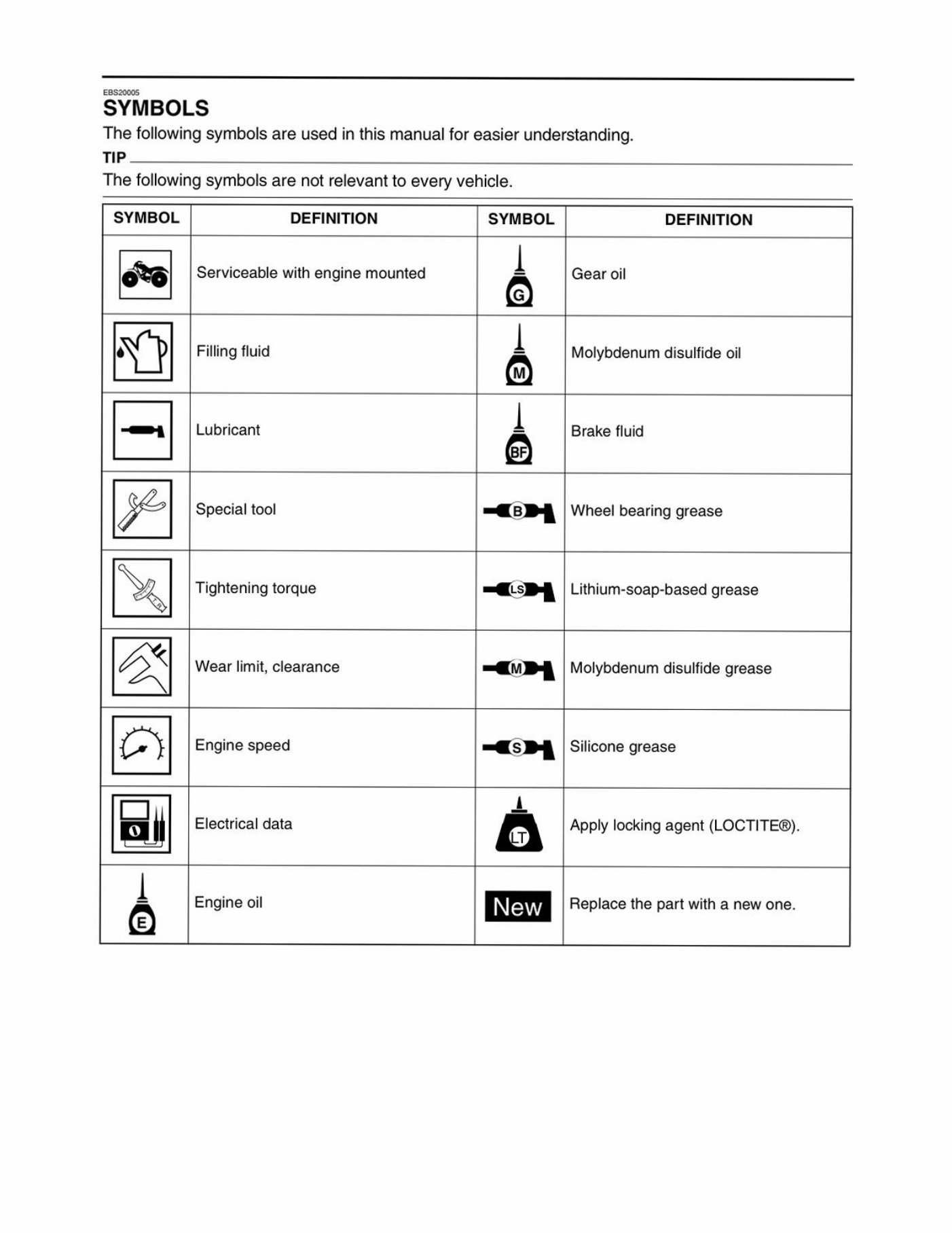
SYMBOLS
Thefollowingsymbolsareusedinthismanualforeasierunderstanding.
TIP
Thefollowingsymbolsarenotrelevanttoeveryvehicle.
SYMBOL
DEFINITION SYMBOL DEFINITION
0%)
Serviceablewithenginemounted
Gearoil
Dp |B |H—
FillingfluidMolybdenumdisulfideoil
LubricantBrakefluid
Specialtool=a5P4Wheelbearinggrease
Tighteningtorque Lithium-soap-basedgrease
Wearlimit,clearance Molybdenumdisulfidegrease
Enginespeed
Siliconegrease
Electricaldata
Applylockingagent(LOCTITE®).
e- (S| DI LIN We
Engineoil
Replacethepartwithanewone.

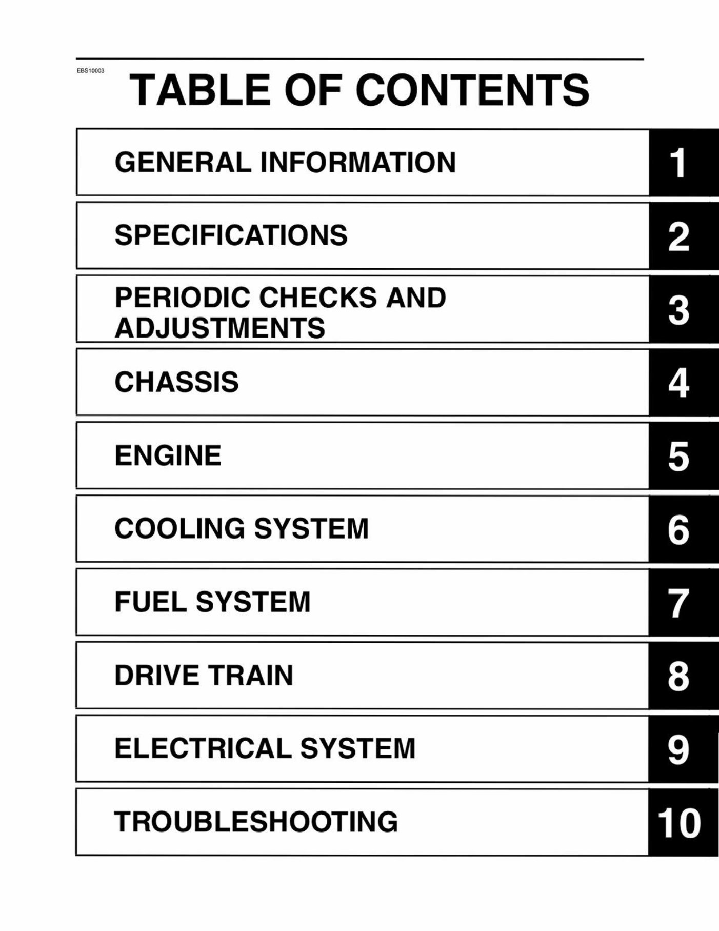
~TABLEOFCONTENTS
GENERALINFORMATION
SPECIFICATIONS
PERIODICCHECKSAND
ADJUSTMENTS
CHASSIS
ENGINE
COOLINGSYSTEM
FUELSYSTEM
DRIVETRAIN
ELECTRICALSYSTEM
TROUBLESHOOTING
lelel~folal=le[s| =

IDENTIFICATION
VEHICLEIDENTIFICATIONNUMBER
MODELLABEL.
FEATURES
INSTRUMENTFUNCTIONS
IMPORTANTINFORMATION...............c:ccccscscscsesssteseessteestenssesestsnsseessneeeseeses
PREPARATIONFORREMOVALANDDISASSEMBLY.
REPLACEMENTPARTG...........0c0000+
GASKETS,OILSEALSANDO-RINGS
LOCKWASHERS/PLATESANDCOTTERPINS
BEARINGSANDOILSEALS
CIRCLIPS.........
RUBBERPARTS.
BASICSERVICEINFORMATION.
QUICKFASTENERS..
ELECTRICALSYSTEM.
SPECIALTOOLS..00....esecccccceccsescseseeeseeceseseseecsseesseesaneesseensnesssesnaneesseenaneees1-11
IDENTIFICATION
eBss0003
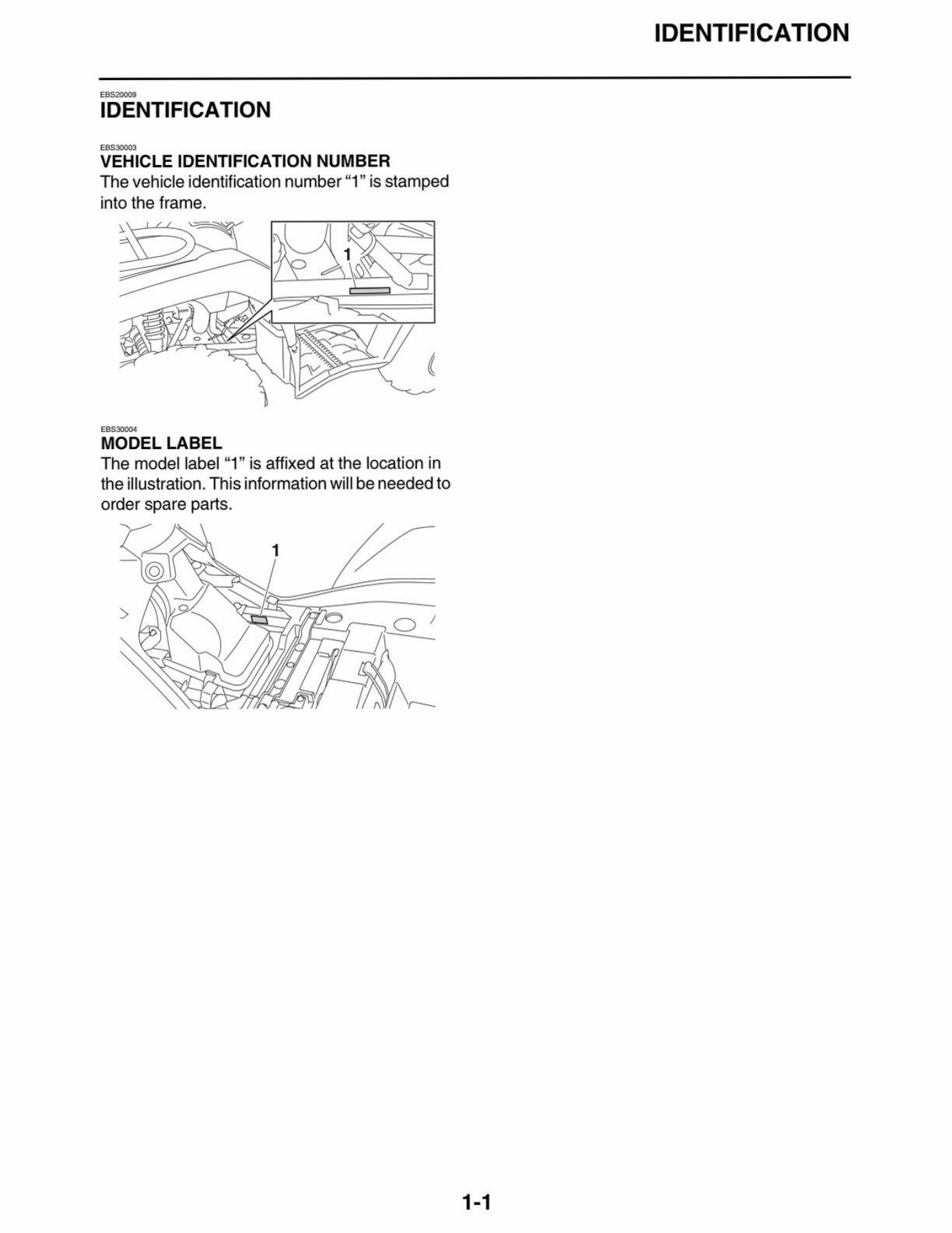
VEHICLEIDENTIFICATIONNUMBER
Thevehicleidentificationnumber“1”isstamped
intotheframe.
MODELLABEL
Themodellabel“1”isaffixedatthelocationin
theillustration.Thisinformationwillbeneededto
orderspareparts.
1-1
IDENTIFICATION
You're Reading a Preview
What's Included?
Fast Download Speeds
Online & Offline Access
Access PDF Contents & Bookmarks
Full Search Facility
Print one or all pages of your manual
$57.99
Viewed 81 Times Today


Secure transaction
What's Included?
Fast Download Speeds
Online & Offline Access
Access PDF Contents & Bookmarks
Full Search Facility
Print one or all pages of your manual
$57.99
The 2024 Yamaha KODIAK 450 EPS Service & Repair Manual provides comprehensive information for both professional mechanics and DIY enthusiasts looking to repair, maintain, or troubleshoot their vehicle.
- This technical guide covers detailed instructions on troubleshooting, repair, and maintenance procedures, making it an essential resource for anyone working with the KODIAK 450 EPS.
- The manual is designed to provide in-depth knowledge of the vehicle's inner workings, including step-by-step guides and diagrams to help you understand and address various issues.
- Suitable for both professionals and DIY enthusiasts, this manual offers a comprehensive overview of the KODIAK 450 EPS's technical specifications, ensuring that you can effectively diagnose and repair any problems that may arise.


