

•
SHOPM
XL35

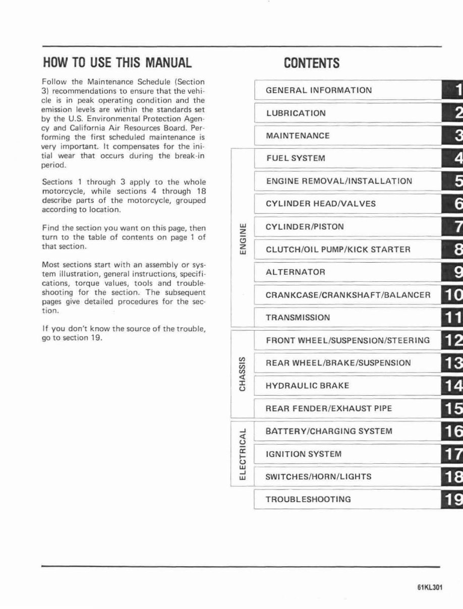
HOW TO USE THI S MANUAL
Follow the Maintenance Schedule (Section
3) recommendations to ensure t hat the veh i-
cle is in peak operat in g co ndit ion and the
emission levels are with in the standards set
by the U.S. Envi ronmental Protection Agen-
cy and California Air Resources Board. Per-
forming the first scheduled maintenance is
very important. It compensates for the ini-
tial wear that occurs during the break-in
period.
Sections 1 through 3 apply to the whole
motorcycle, while sections 4 through 18
describe parts of the motorcycle, gr ouped
according to location.
Find the section you want on this page, then
turn to the table of contents on page 1 of
that section.
Most secti ons start with an assembly or sys-
tem illustrati on, general instructions, specifi-
cations, torque va lues, tools a nd tro uble-
shooting for the section. The subsequent
pages give detailed procedures for the sec-
tion.
If you don't know the source of the trouble ,
go to section 19 .
w
2
"
2
w
..J
~
u
a:
....
u
W
..J
W
CONTENTS
GENERAL INFORMATION
LUBRICATION E
MAINTENANCE E
FUEL SYSTEM
ENGINE REMOVALIINSTALLATION =--
CYLINDER HEADIVALVES lIS;
CYLINDER / PISTON
CLUTCH / OIL PUMP / KICK STARTER
ALTERNATOR
CRANKCASE/ CRANKSHAFT / BALANCER
TRANSMISSION
FRONT WHEEL/SUSPENSION/STEERING
REAR WHEEL/BRAKE /SUSPENSION
HYDRAULIC BRAKE
REAR FENDER / EXHAUST PIPE
BATTERY /CHARGING SYSTEM
IGNITION SYSTEM
SW ITCH ES /HOR N/ L1 GHTS
TROUBLESHOOTING
61KU01

,
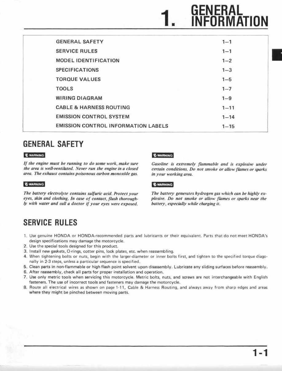
GENERAL SAFETY
SERVICE RULES
MODEL IDENTIFICATION
SPECIFICATIONS
TORQUE VALUES
TOOLS
WIRING DIAGRAM
CABLE & HARNESS ROUTING
EMISSION CONTROL SYSTEM
1.
GENERAL
INFORMATION
EMISSION CONTROL INFORMATION LABELS
1-1
1-1
1-2
1-3
1-5
1- 7
1-9
1-11
1-14
1- 15
GENERAL SAFETY
(4id;liliiitj
If Ihe engine must be running to do some work, moke sure
the area ;s well· ventilated. Nellf!r run the engine in a closed
area, The exhaust contains poisonous corbon m onoxtde gas.
h'i/.l@@'
The battery electrolyle contains sulfuric acid. Protect your
eyes, skin and clothing. In case of contact, flush thorough-
ly with worer and call Q doctor if your eyes were exposed.
SERVICE RULES
Gasoline is extremely flommable and is explosi ve under
cerrain conditions, Do not smoke or allow {/Qmes or sparks
in yo ur working area.
'CI;i!i!ii1
The battery generales hydrogen gas whi ch CfIn be highly ex-
plasi,,€!. Do not smoke or allow flames or sparks near the
ba ttery. especially while charging it.
1. Use genuine HONDA or HONDA·recommended parts and lubricants or their equivalent. Parts that do not meet HONDA's
design specifications may damage the motorcycle.
2. Use the special tools designed for this product.
3. Install new gaskets, O .... ings, cotter pins, lock plates, etc. when reassembling.
4. When tightening bolts or nuts, begin with the larger-diameter or inner bolts first, and tighten to the specified torque diago·
nally in 2-3 steps, unless a particular sequence is spec ifi ed .
5. Clean parts in non-flammable or high flash point solvent upon disassembly. Lubricate any sliding surfaces before reassembly_
6. After reassembly. check all parts for proper installation and operation.
7. Use only metric tools when servicing this motorcycle. Metric bolts, nuts, and screws are not interchangeable with English
fasteners. The use of incorrect tools and fasteners may damage the motorcycle.
8. Route all f'lectrical wires as shown on page 1·11, Cable & Harness Rout ing, and always away from sharp edges and areas
where they might be pinched between moving parts.
1-1
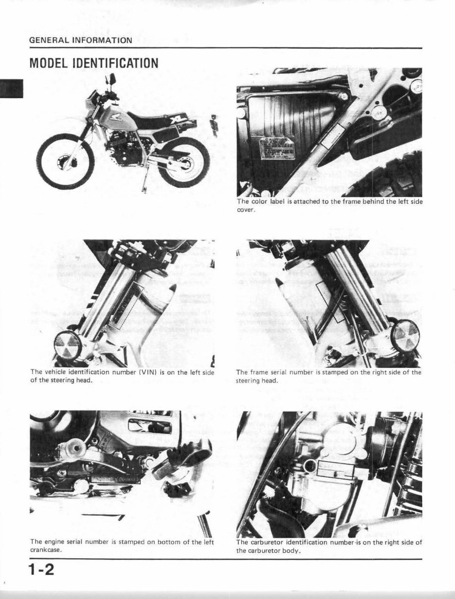
GENERAL INFORMATION
MODEL IDENTIFICATION
The vehicle identification number (V IN) is on the left side
of the steering head.
,
The engine serial number is stamped on bottom of the left
crankcase.
1-2
rz n ~
cover.
,\
The frame serial
steering head.
,
,.
is attached to th " T.;;;;~
0;;;,,,,,;; identification number·is on the right side of
the carburetor body.
GENERAL INFORMATION
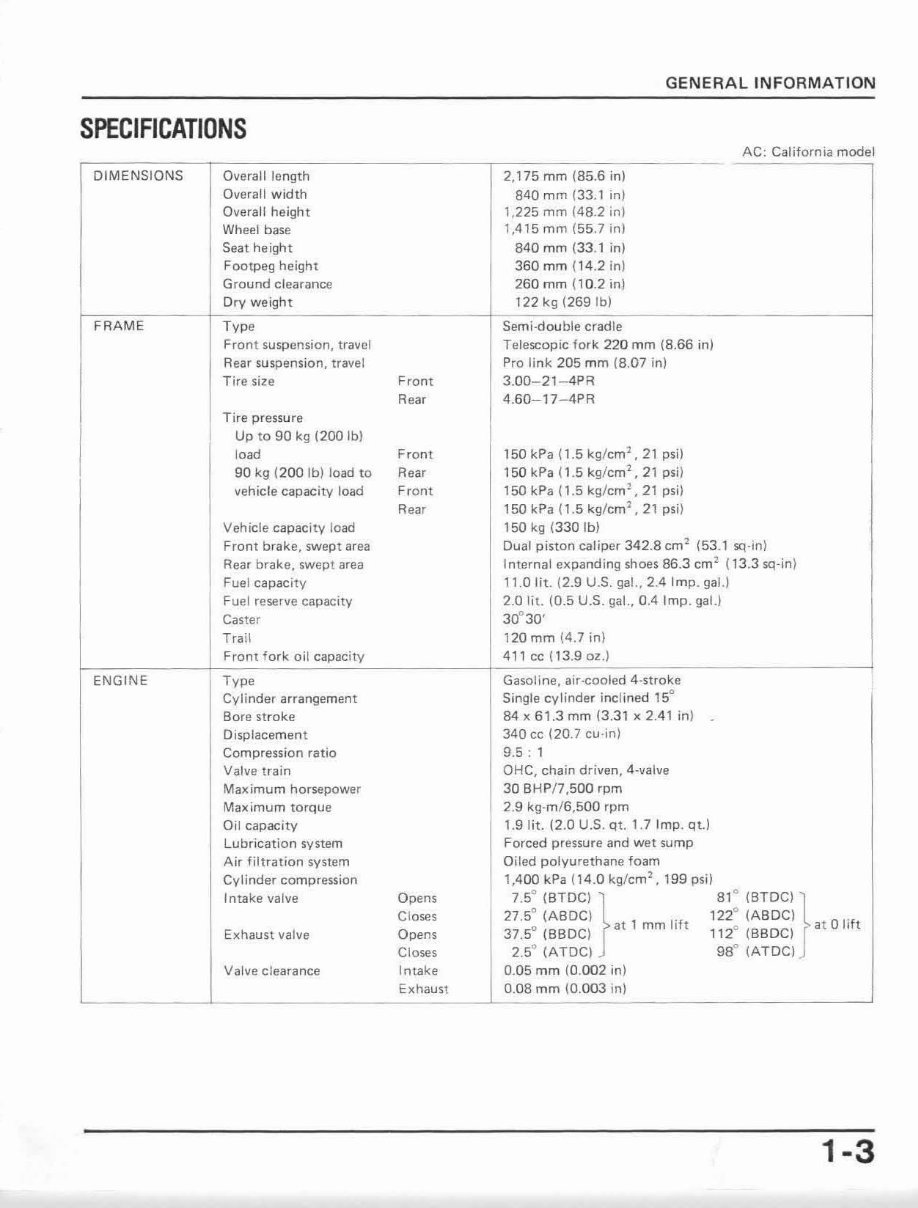
SPECIFICATIONS
AC' California model
DIMENSIONS Overall length 2,175 mm (85.6 in)
Overall width 840 mm (33.1 In)
Overall height 1,225 mm (48.2 in)
Wheel base
, ,415 mm (5 5.7 in)
Seat height 840 mm (33.1 in)
Footpeg height 360 mm (14.2 in)
Ground clearance 260 mm (1 0.2 in)
Dry weight t 22 kg (269 Ibl
FRAME Type Semi·double cradle
Front suspension, travel Telescopic fork 220 mm (8.66 in)
Rear suspension, travel Pro link 205 mm (8.07 in)
Tire size Front 3.00-21-4PR
Rear 4.60-17-4PR
Tire pressure
Up to 90 kg (200 Ibl
load Front 150 kPa (1.5 kg/cm
1
, 21 psi)
90 kg (200 Ib) load to Rear 150 kPa 11.5 kg/cm
2
• 21 psi)
vehicle capacity load Front 150 kPa (1.5 kg/cm
l
, 21 psi)
Rear 150 kPa (1.5 kg/cm
2
, 21 psi)
Vehicle capacity load 150 kg (330 Ib)
Front brake, swept area Dual piston caliper 342.8 cm
2
(53.1 sq·in)
Rear brake, swept area Internal expanding shoes 86.3 cm
2
(13.3 sq·in)
Fuel capacity 11.0 lit. (2.9 U.S. gal., 2.4 Imp. gaLl
Fuel reserve capacity 2.0 lit. (0.5 U.S. gal., 0.4 Imp. gal.)
Caster 30° 30'
Trail 120mm (4.7 in)
Front fork oil capacity 4'1 cc (13.90z.J
ENGINE Type Gasoline, air-cooled 4-stroke
Cylinder arrangement Single cylinder inclined 15°
Bore stroke 84 x 61.3 mm (3.31 x 2.41 in)
Displacement 340 cc (20.7 cu·in)
Compression ratio 9.5 : 1
Valve train OHC, chain driven, 4-valve
Maximum horsepower 30 BHP/7,500 rpm
Maximum torque 2.9 kg-m/G ,SOO rpm
Oil capacity 1.9 l it. (2.0 U.S. qt. 1.7 Imp. qt.)
Lubrication system Forced pressure and wet sump
Air filtration system Oiled polyurethane foam
Cylinder compression 1,400 kPa (1 4 .0 kg/cm
2
, 199 psi)
Intake valve Opens
7.5
0
(BTOC) } 8, 0 )BTDCI }
Cl oses 27.5° (ABDCI ,
mm lift
122
0
(ABDC) .
Exhaust valve Opens
37.5° (BBDC) at
1120 (BBDC) at a 11ft
Closes 2.5" (ATDC) 98° (ATDC)
Valve clearance Intake 0.05 mm (0. 002 in)
Exhaust 0.08 mm (0. 003 in)
1-3
GENERAL INFORMATION
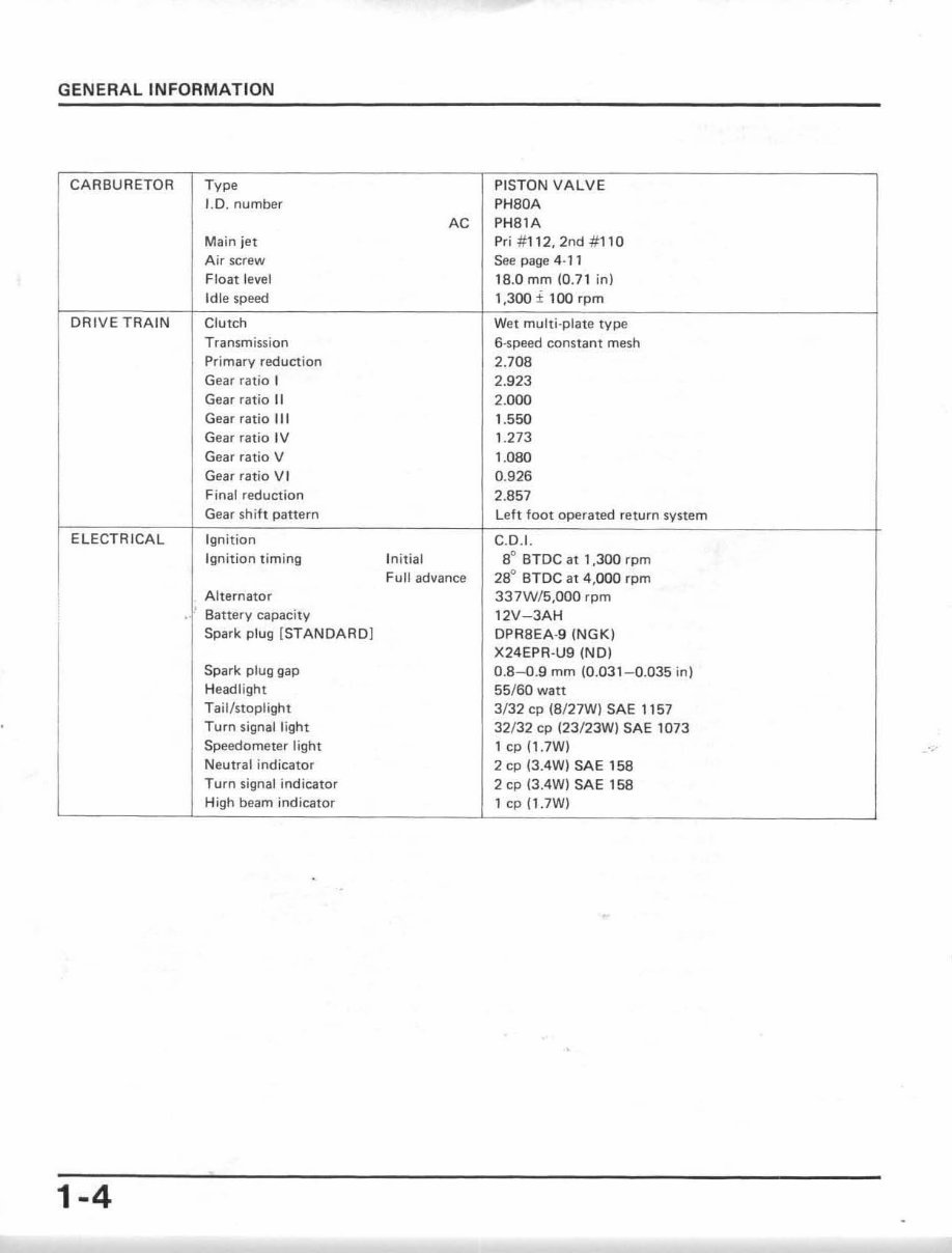
CARBURETOR Type PISTON VALVE
1.0. number PH80A
AC PH81A
Main jet Prj # 112, 2nd #1 10
Air screw See page 4·11
Float level 18.0 mm (0.7 1 in)
Idl e speed 1,300 ± 100 rpm
DRIVE TRAIN Clutch Wet multi-plate type
Transmission 6 -s peed constant mesh
Primary reduction 2.708
Gear ratio I 2.923
Gear ratio II 2.000
Gear ratio III 1.550
Gear ratio IV 1.273
Gear ratio V 1.080
Gear ratio V I 0.926
Final reduction 2.857
Gear sh i ft pattern Left foot operated return system
ELECTRICAL Ign ition C.D. 1.
Ignition timing Initial a
O
BTDC at 1,300 rpm
Full advance 28° BrDC at 4,000 rpm
Alternator 337W/ 5,OOO rpm
. ' Batte ry capacity 12V- JAH
Spark plug { STANDARD] OPR8EA-9 (NGK)
X24EPR· U9 (NO)
Spark plug gap 0. 8-0 .9 mm (0.031- 0.035 in)
Headlight 55/ 60 watt
Tail/stoplig ht 3/ 32 cp (S/27W) SAE 1157
Turn sign al light 32/ 32 cp (23/23W) SAE 1073
Speedometer light 1 cp (l .7W)
Neutral i nd ica tor 2 cp (3AW) SAE 158
Turn signal indicator 2 cp (JAW) SAE 158
High beam in dicator 1 cp (1 .7W)
1-4
GENERAL INFORMATION
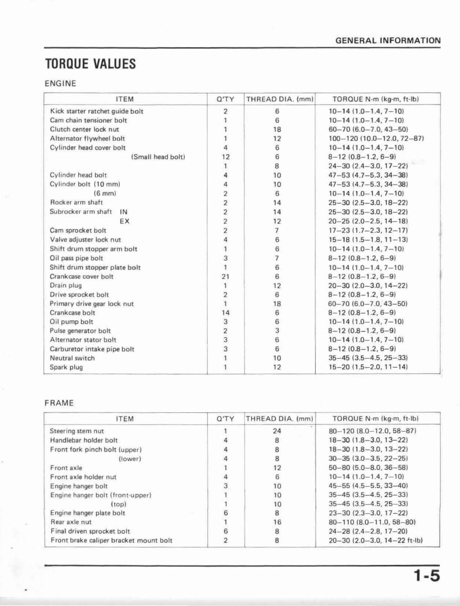
TORQUE VALUES
ENGINE
ITEM a'TY THREAD OIA . (mm) TO ROUE N·m (kg-m, ft-Ib)
Kick starter ratchet guide bolt 2 6 10- 14 11.0- 1.4,7- 10 )
Cam chain tensioner bolt 1 6 10-1411.0-1.4,7-10)
Clutch center lock nut 1 18 60-70 (6.0- 7.0, 43 - 50)
Alternator flywheel bolt 1 12 100- 120110.0-12.0,72-871
Cylinder head cover bolt
•
6 10- 1411.0-1.4,7-10)
(Small head bolt) 12 6 8- 1210. 8-1.2.6-9)
1 8 24-30 (2.4-3. 0,17 -22)
Cylinder head bolt
•
10 47 - 53 (4 .7-5.3, 34-38)
Cvlinder bolt ( 10 mm)
•
10 47-5314.7-5.3,34-38)
(Smm) 2 6 10- 14 11.0- 1.4,7 - 10 )
Rocker arm shaft
2 I. 25-30 (2.5-3.0, 18 -221
Subrocker arm shaft IN 2 I. 25-30 12.5- 3.0, 18-221
EX 2 12 20-2512.0-2.5, 14- 18)
Cam sprocket bolt 2 7 17- 23 (1.7-2.3, 12-17)
Valve adjuster loclt nut
•
6 15- 18 11.5-1.8, 11 - 13)
Shift drum stopper arm bolt 1 6 10-1411.0-1.4 , 7-10 )
Oil pass pipe bolt 3 7 8- 12 (0.8-1.2,6-9)
Shift drum stopper plate bolt 1 6 10-14 (1.0- 1.4, 7- 10)
Crankcase cover bolt 21 6 8- 12 10.8- 1.2, 6-9 )
Dram plug 1 12 20-30 (2.0-3 .0 , 14-22)
Dr ive sprocket bolt 2 6 8-12 (0.8- 1.2, 6-9 )
Primary drive gear lock nut 1 18 60- 70 (6.0-7.0, 43 - 501
Crankcase bolt I. 6 8- 12 10.8-1 .2, 6-9 )
Oil pump bolt 3 6 10- 14 (1.0- 1.4, 7-10)
Pulse generator bolt 2 3 8- 12 (0.8- 1.2, 6-9)
Alternator stator bolt 3 6 10-1411.0-1.4 , 7- 101
Carburetor intake pipe bolt 3 6 8-12 (0.8- 1. 2,6-9)
Neutral switch 1 10 35- 45 (3.5-4.5, 25 - 33)
Spark plug 1 12 15- 20 (1.5- 2.0, 11 - 14)
FRAME
ITEM O' TY THREAD DIA. (mm ) TOROUE N ·m (kg-m, ft -Ib )
Steering stem nut 1 2. 80- 120 (8.0-12.0, 58- 871
Handlebar holder bolt 4 8
18-30 (1.8-3.0, 13-22 )
Front fork pinch bolt (upper)
•
8
18- 30 ( 1.8-3.0, 13-22)
(lower)
•
8 30- 35 13.0- 3.5 , 22-25 )
Front axle 1 12 50- 80 (5.0-8.0, 36 - 58)
Fro nt axle holder n ut
•
6 10-1411.0-1.4.7- 10)
Engine hanger bolt 3 10 45- 55 14.5-5.5,33-40)
Engine hanger boll (front - upper) 1 10 35-45 (3.5-4 .5, 25-33)
(top) 1 10 35-45 13.5- 4.5, 25- 33)
Engine hanger plate bolt 6 8 23-30 12.3- 3.0, 17- 22)
Rear axle nut 1 16 80- 110 (8.0- 11.0, 58- 80)
Final driven sprocket bolt 6 8 24- 2812.4- 2.8,17 - 20)
Front brake ca li per bracket mount bolt 2 8 20- 30 (2.0-3.0, 14 - 22 ft -Ib)
1-5
GENERAL INFORMATION
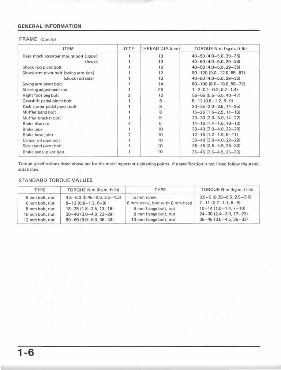
FRAME (Cont'd)
ITEM O'TY I-rHREAD DIA.(mm TORQUE N·m (kg-m. ft -Ib )
Rear shock absorber mount bolt (upper) 1 10 40 -50 (4.0-5.0, 29- 36)
(tower) 1 10 40-50 14.0- 5.0, 29-36)
Shock rod pillot boh 1 10 40- 50 (4.0-5.0.29-36)
Shock. arm pillat bolt (swing arm side) 1 12 90- 120 (9.0- 12.0, 65-871
(shock rod side) 1 10 40- 50 (4 .0-5.0, 29-36)
Swing arm pivot bolt 1
,.
80- 100 (8.0-10.0, 58-72)
Steering adjustment nut 1 26 1-2 (0.1- 0.2.0.7-1.4)
Aight foot peg bolt 2 10 55- 6515.5-6.5,40-47)
Gearshift pedal pinch bolt 1 6 8- 12 (0.8- 1.2. 6- 9)
Kick starter pedal pinch bo lt 1 8 20- 35 (2.0-3.5, 14-25)
Muffler band bolt 1 8 15-25 (1 .5-2. 5, 11 - 18)
Muffler bracket bolt 1 8 20- 30 (2.0-3.0, 14-221
Brake disc nut
•
6 14 - 160.4 - 1.6. 10- 12)
Brake pipe 1 10 30-40 (3.0-4.0, 22-29)
Brake hose joinl 2 10 12-15 (1.2-1.5, 9-11)
Caliper oil pipe boh 1 10 30-40 13.0-4.0, 22-291
Side stand pivot bolt 1 10 35-45 (3.5- 4.5, 25-33)
Brake pedal pivot bolt 1 10 35 - 45 13 . 5-4.5, 25-33}
Torque specifications listed above are for the most important t igh tening points. If II specificat ion is not listed follow the stand·
ards below.
STANDARD TORQUE VA LUES
TYPE TORQUE N·m (kg·m, ft·lb) TYPE TORQUE N'm Ikg·m, ft·lb)
5 mm bolt, nut 4 .5-6.0 (0.45--0.6, 3.3-4.3) 5 mm saew 3.5-5 10.35-0.5, 2.5-3.61
6 mm bolt, nut 8-12 10.8-1.2, 6-91 6 mm screw, bolt with 8 mm head 7- 11 (0.7 -1.1, 5-8 )
8 mm bott, nut 18-2511 .8 -2.5, 13- 181 6 mm flange bott, nut 10- 14 (1.0-1.4, 7-10)
10 mm bolt, nut 30-40 (3.0-4.0, 22-29) 8 mm flange bott, nut 24-30 (2.4-3.0, 17-221
12 mm bolt, nut 50- 60 (5.0-6. 0, 36- 431 10 mm flange bolt, nut 35-45 (3.5-4.5, 25- 33)
1-6
You're Reading a Preview
What's Included?
Fast Download Speeds
Online & Offline Access
Access PDF Contents & Bookmarks
Full Search Facility
Print one or all pages of your manual
$31.99
$41.99
1984-1985 XL350R XL350 Service & Repair Manual
Viewed 85 Times Today

What's Included?
Fast Download Speeds
Online & Offline Access
Access PDF Contents & Bookmarks
Full Search Facility
Print one or all pages of your manual
$31.99
$41.99

Secure transaction
What's Included?
Fast Download Speeds
Online & Offline Access
Access PDF Contents & Bookmarks
Full Search Facility
Print one or all pages of your manual
- This repair manual is for the 1984-1985 Honda XL350R four-stroke dual sport bike.
- It covers complete tear down and rebuild, including pictures and part diagrams, torque specs, maintenance, troubleshooting, and more.
- The manual is 232 pages long and has clickable chapters, making it easy to navigate.
- It is also searchable, allowing users to quickly find the information they need.
- There are no restrictions on printing or saving/burning to disc.
- This manual is useful for both professional mechanics and DIY enthusiasts.


