

Bosch Diesel Injection Pumps Size A, B, K and Z Repair
What's Included?
Fast Download Speeds
Online & Offline Access
Access PDF Contents & Bookmarks
Full Search Facility
Print one or all pages of your manual
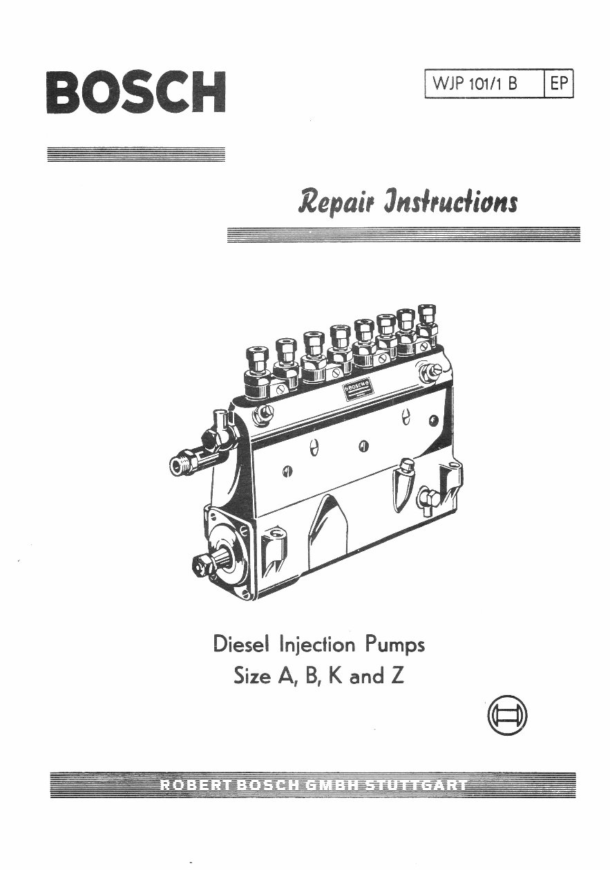
BOSCH
WJP 101/1 B EP
Repair 3nsieuclions
Diesel Injection Pumps
Size A, B, K and Z
Table of Contents
Page
I. Introduction 1
II. Initial Examination 2
A) Without pump being removed 2
B) With pump removed 3
III. Dismantling 4
A) Sequence of Operations on Pumps
Type PE 4
B) Sequence of Operations on Pumps
Type PF 13
IV. Repair and Replacement 14
A) Elements 14
B) Delivery Valve 14
C) Roller Tappet or Plunger Guide 14
D) Camshaft 14
E) Ball Bearings 15
F) Control Rod 15
G) Control Quadrant and Sleeve 15
H) Plunger Spring 15
I) Pump Hoys . ing 15
V. Assembly 16
A) Assembly Numbers 16
B) Sequence of Operations for Assembly 16
VI. Special Tools and Appliances 26
VII. Tightening Torques 28
VIII. Explanation of Injection Pump Marks 30
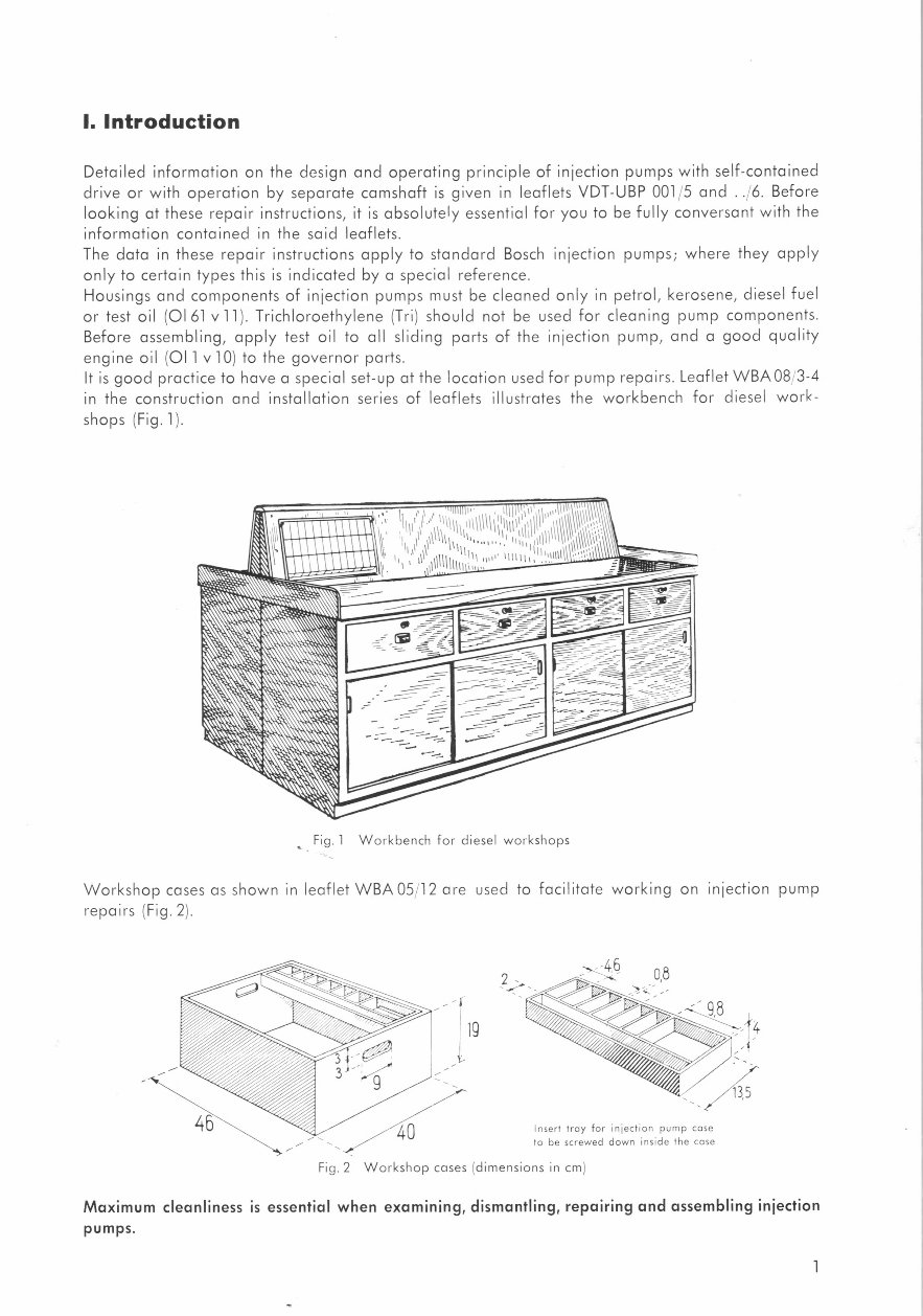
I. Introduction
Detailed information on the design and operating principle of injection pumps with self-contained
drive or with operation by separate camshaft is given in leaflets VDT-UBP 001,5 and .. 6. Before
looking at these repair instructions, it is absolutely essential for you to be fully conversant with the
information contained in the said leaflets.
The data in these repair instructions apply to standard Bosch injection pumps; where they apply
only to certain types this is indicated by a special reference.
Housings and components of injection pumps must be cleaned only in petrol, kerosene, diesel fuel
or test oil (01 61 vii). Trichloroethylene (Tr) should not be used for cleaning pump components.
Before assembling, apply test oil to all sliding parts of the injection pump, and a good quality
engine oil (011 v10) to the governor parts.
It is good practice to have a special set-up at the location used for pump repairs. Leaflet WBA 08 3-4
in the construction and installation series of leaflets illustrates the workbench for diesel work-
shops (Fig. 1).
Fig. 1 Workbench for diesel workshops
Workshop cases as shown in leaflet WBA 05 12 are used to facilitate working on injection pump
repairs (Fig. 2).
lg
Insert tray for injection pump case
to be screwed down inside the case
Fig. 2 Workshop cases (dimensions in cm)
Maximum cleanliness is essential when examining, dismantling, repairing and assembling injection
pumps.
1
II. Initial Examination
A) Without pump being removed
For tracing trouble and detecting a fault in the injection system of an engine, a test run or trial
trip should be made before removing the injection pump, followed by a visual test. Only then
should a decision be made as to the necessity of removing the injection pump. If it has already
been removed, a check of the pump on the test bench is generally advisable. Only then should
the injection pump be dismantled.
The following sequence of operations is advisable for PE-pumps (this largely applies likewise to
PF-pumps):
1. Before removing it, check whether the pump specified by the engine manufacturer for the
respective engine has been installed. Compare type formula with the design of the pump, check
position of camshaft or cam sequence (watch direction of rotation) and check position of
governor, injection timer and feed pump (for assembly figures see page 30).
2 Check full-load stop on governor and control rod stop on pump for correct setting and sealing
(on pneumatic governors also check stops of Venturi control unit). Check whether fixing screws
of endplate and of governor housing are still secured.
Check whether, when depressing the pedal, the control lever of the centrifugal governor rests
against the full-load stop. Unhinge the linkage and check control rod for smooth action. Un-
screw inspection cover of injection pump, move control lever of governor to FULL and see
whether the deflection of all control sleeves with control quadrants is the same.
Check whether marks on control sleeves and control quadrants coincide and whether clamping
screws are tightened. Check that lock nut of tappet screw is tight. See whether surface of tappet
springs is still satisfactory or if they are damaged.
If any resistance is detected on the control lever of a governor, continue to push with control-
rod stop fixed until the idling springs of the governor are fully compressed and strong resistance
is perceptible. In this position, the control lever should just touch the full-load stop screw.
In case of an automatic (resilient) stop for additional fuel delivery, after reaching the first resis-
tance, hold back the control rod by means of the control sleeves (pushing them strongly upwards),
then continue pushing the lever until the idling springs are compressed. In this position, the
control lever should just touch the full-load stop screw.
On pneumatic governors, the control lever is normally always set to FULL ; check whether here,
too, the deflection of all control sleeves with control quadrants is the same. In normal conditions,
the control rod must rest against the stop at roughly half the control rod travel.
3. In the event of difficulties in starting, the engine should be checked for correct compression and
correct starting speed. If these are found to be in order, look for the defect on the pump.
Here a check should be made as to whether the element produces pressure by priming the pump
element through the roller tappet at full-load position of the pump with a broad, non-resilient
screwdriver or better still with pump primer lever EFEP 222 (Fig. 3).
A perceptible resistance when pushing the elements upwards indicates that the elements and
nozzles are in good order. If pushing does not produce any resistance, detach delivery pipe and
close the pump outlets (with pinched-off pipes or with injection tester EFEP 66 A). Repeat this
operation.
If pressure then exists, the nozzle will no longer close. Where no pressure exists, the delivery
valve is jammed (open) or the element is useless.
If, however, everything is in good order, check heater plugs or heating flange and compression.
2
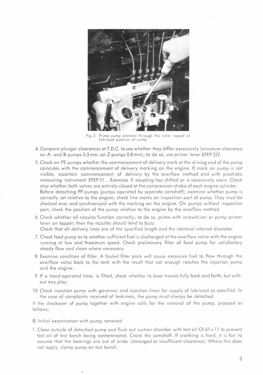
Fig. 3 Prime pump element through the roller tappet at
full-load position of pump
4. Compare plunger clearances at T.D.C. to see whether they differ excessively (minimum clearance
on A- and B-pumps 0.3 mm, on Z-pumps 0.8 mm) ; to do so, use primer lever EFEP 222.
5. Check on PE-pumps whether the commencement of delivery mark at the driving end of the pump
coincides with the commencement of delivery marking on the engine. If mark on pump is not
visible, ascertain commencement of delivery by the overflow method and with prestroke
measuring instrument EFEP 51.. Examine if coupling has shifted or is excessively worn. Check
also whether both valves are entirely closed at the compression stroke of each engine cylinder.
Before detaching PF-pumps (pumps operated by separate camshaft), examine whether pump is
correctly set relative to the engine ; check line marks on inspection port of pump. They must be
checked over and synchronized with the marking on the engine. On pumps without inspection
port, check the position of the pump relative to the engine by the overflow method.
6. Check whether all nozzles function correctly ; to do so, prime with screwdriver or pump primer
lever on tappet ; then the nozzles should tend to buzz.
Check that all delivery lines are of the specified length and the identical internal diameter.
7. Check feed pump as to whether sufficient fuel is discharged at the overflow valve with the engine
running at low and i -naximum speed. Check preliminary filter of feed pump for satisfactory
steady flow and clean where necessary.
8. Examine condition of filter. A fouled filter pack will cause excessive fuel to flow through the
overflow valve back to the tank with the result that not enough reaches the injection pump
and the engine.
9. If a hand-operated time' . is fitted, check whether its lever travels fully back and forth, but with-
out any play.
10. Check injection pump with governor and injection timer for supply of lubricant as specified In
the case of complaints received of leakiness, the pump must always be detached.
If the checkover of pump together with engine calls for the removal of the pump, proceed as
follows:
B) Initial examination with pump removed
1. Clean outside of detached pump and flush out suction chamber with test oil 01 61 v 11 to prevent
test oil of test bench being contaminated. Crank the camshaft. If cranking is hard, it is fair to
assume that the bearings are out of order (damaged or insufficient clearance). Where this does
not apply, clamp pump on test bench.
3
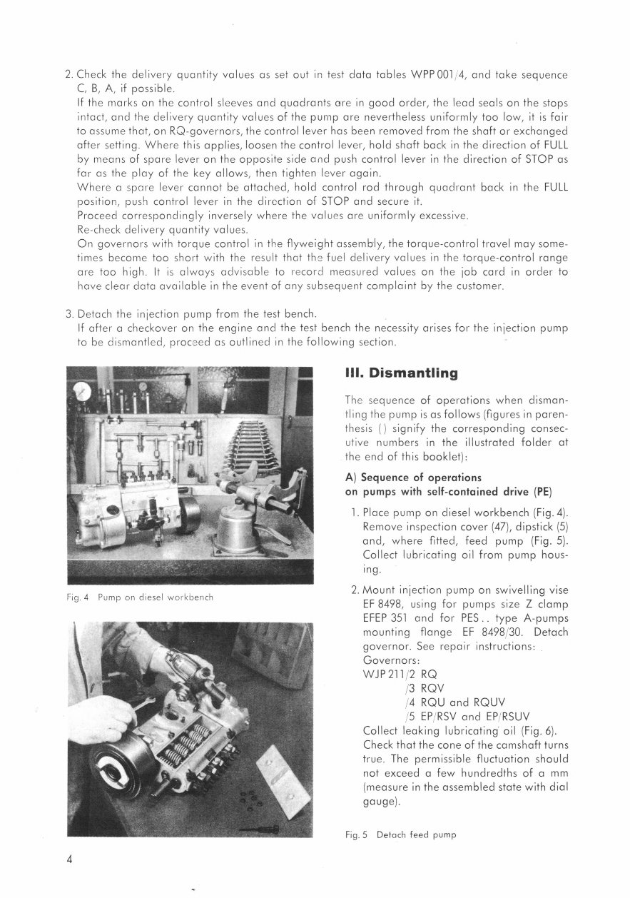
Fig. 4 Pump on diesel workbench
4
2 Check the delivery quantity values as set out in test data tables WPP 001 4, and take sequence
C, B, A, if possible.
If the marks on the control sleeves and quadrants are in good order, the lead seals on the stops
intact, and the delivery quantity values of the pump are nevertheless uniformly too low, it is fair
to assume that, on RO-governors, the control lever has been removed from the shaft or exchanged
after setting. Where this applies, loosen the control lever, hold shaft back in the direction of FULL
by means of spare lever on the opposite side and push control lever in the direction of STOP as
far as the play of the key allows, then tighten lever again.
Where a spare lever cannot be attached, hold control rod through quadrant back in the FULL
position, push control lever in the direction of STOP and secure it.
Proceed correspondingly inversely where the values are uniformly excessive.
Re-check delivery quantity values.
On governors with torque control in the flyweight assembly, the torque-control travel may some-
times become too short with the result that the fuel delivery values in the torque-control range
are too high. It is always advisable to record measured values on the job card in order to
have clear data available in the event of any subsequent complaint by the customer.
3. Detach the injection pump from the test bench.
If after a checkover on the engine and the test bench the necessity arises for the injection pump
to be dismantled, proceed as outlined in the following section.
Ill. Dismantling
The sequence of operations when disman-
tling the pump is as follows (figures in paren-
thesis ( ) signify the corresponding consec-
utive numbers in the illustrated folder at
the end of this booklet):
A) Sequence of operations
on pumps with self-contained drive (PE)
1. Place pump on diesel workbench (Fig. 4).
Remove inspection cover (47), dipstick (5)
and, where fitted, feed pump (Fig. 5).
Collect lubricating oil from pump hous-
ing.
2. Mount injection pump on swivelling vise
EF 8498, using for pumps size Z clamp
EFEP 351 and for PES .. type A-pumps
mounting flange EF 8498'30. Detach
governor. See repair instructions:
Governors:
WJP 211/2 RQ
/3 RQV
4 RQU and RQUV
5 EP RSV and EP RSUV
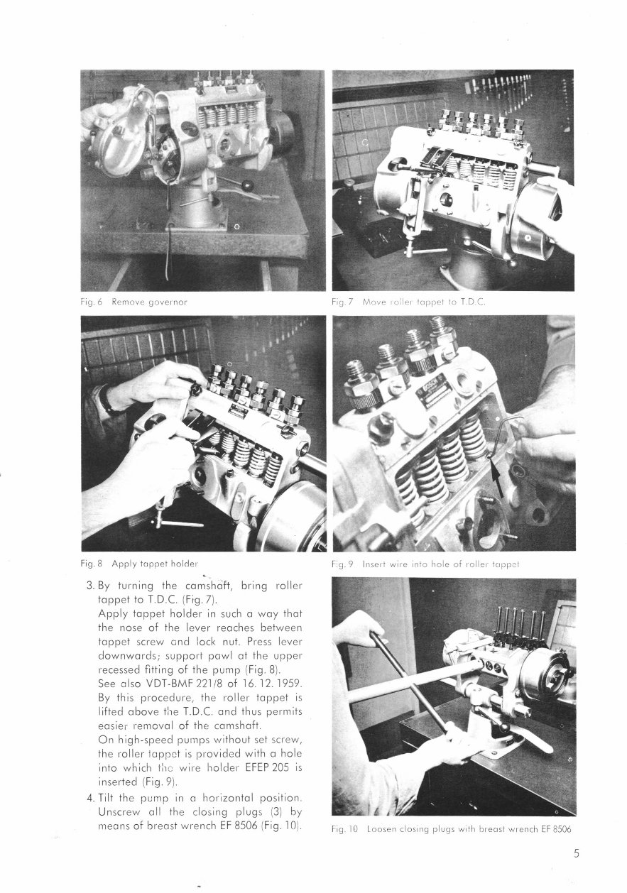
Collect leaking lubricating . oil (Fig. 6).
Check that the cone of the camshaft turns
true. The permissible fluctuation should
not exceed a few hundredths of a mm
(measure in the assembled state with dial
gauge).
Fig. 5 Detach feed pump
41 -
F g. 9 Insert wire into hole of roller toppei Fig. 8 Apply tappet holder
Fig. 6 Remove governor Fig. 7 Move roIler tappet to T.D.C.
3. By turning the camshaft, bring roller
tappet to T.D.C. (Fig. 7).
Apply tappet holder in such a way that
the nose of the lever reaches between
tappet screw cnd lock nut. Press lever
downwards ; support pawl at the upper
recessed fitting of the pump (Fig. 8).
See also VDT-BMF 221/8 of 16.12. 1959.
By this procedure, the roller tappet is
lifted above the T.D.C. and thus permits
easier removal of the camshaft.
On high-speed pumps without set screw,
the roller lappet is provided with a hole
into which thc wire holder EFEP 205 is
inserted (Fig. 9).
4. Tilt the pump in a horizontal position.
Unscrew all the closing plugs (3) by
means of breast wrench EF 8506 (Fig. 10).
Fig. 10 Loosen closing plugs with breast wrench EF 8506
5
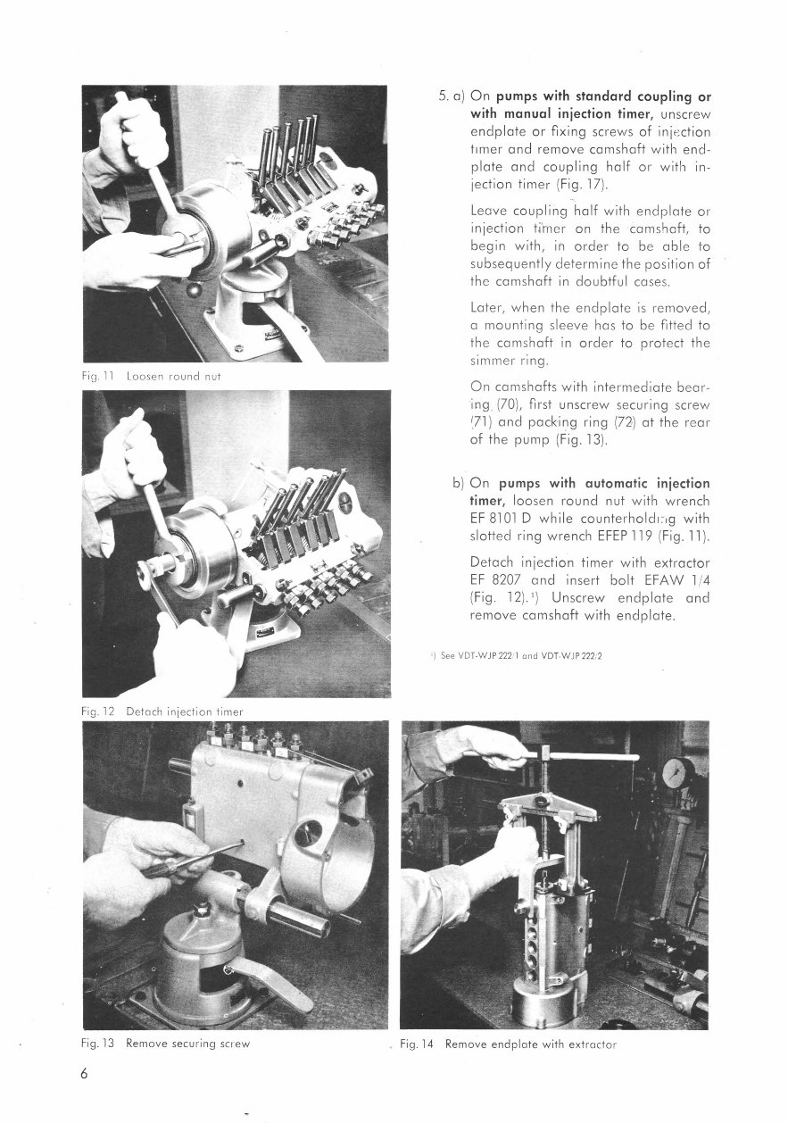
Fig. 11 Loosen round nut
Fig. 12 Detach injection timer
5. a) On pumps with standard coupling or
with manual injection timer, unscrew
endplate or fixing screws of injection
timer and remove camshaft with end-
plate and coupling half or with in-
jection timer (Fig. 17).
Leave coupling half with endplate or
injection timer on the camshaft, to
begin with, in order to be able to
subsequently determine the position of
the camshaft in doubtful cases.
Later, when the endplate is removed,
a mounting sleeve has to be fitted to
the camshaft in order to protect the
simmer ring.
On camshafts with intermediate bear-
ing (70), first unscrew securing screw
(71) and packing ring (72) at the rear
of the pump (Fig. 13).
b) On pumps with automatic injection
timer, loosen round nut with wrench
EF 8101 D while counterholdr - ig with
slotted ring wrench EFEP 119 (Fig. 11).
Detach injection timer with extractor
EF 8207 and insert bolt EFAW 1/4
(Fig. 12).9 Unscrew endplate and
remove camshaft with endplate.
See VDT-WJP 222 1 and VDT-WJP 222 , 2
Fig. 13 Remove securing screw Fig. 14 Remove endplate with extractor
6
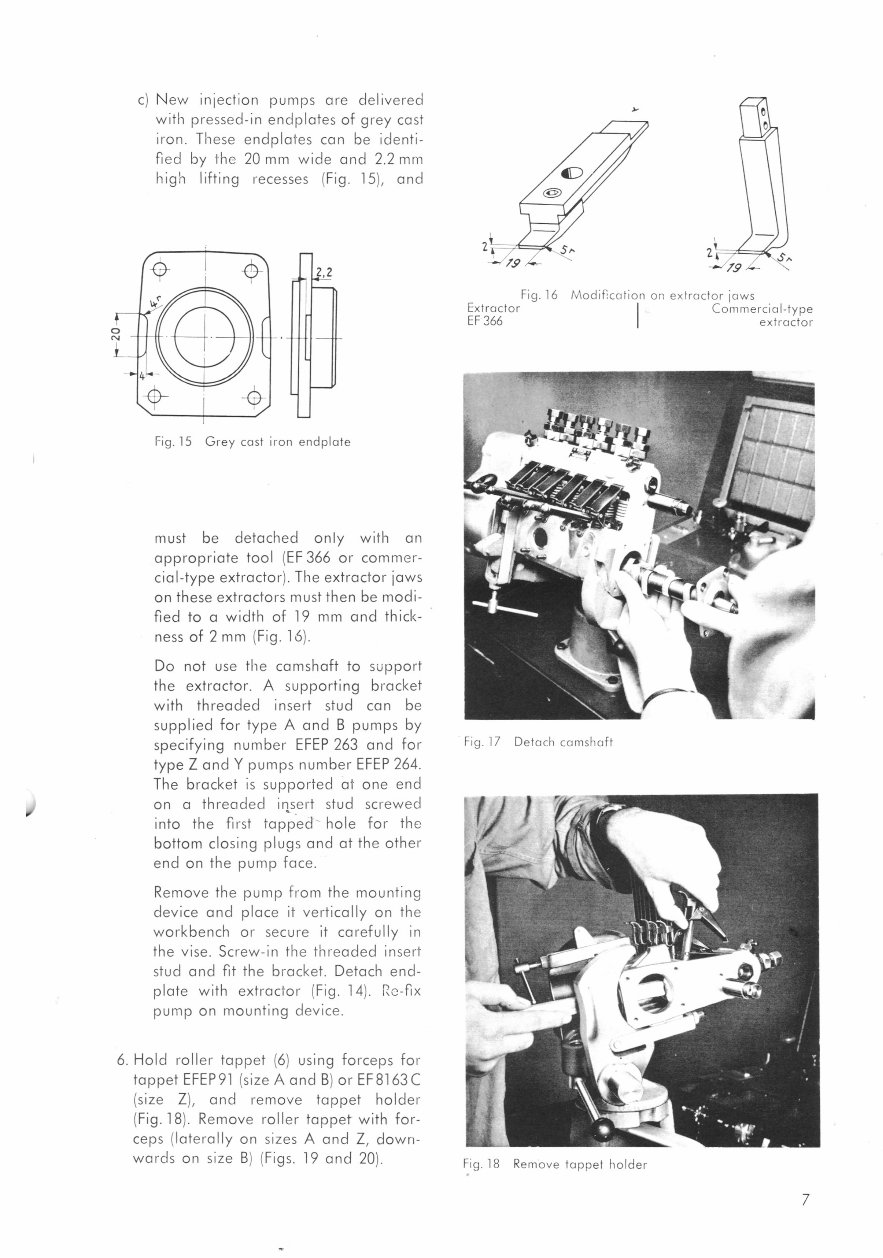
Fig. 16 Modification on extractor jaws
Extractor
EF 366
Commercial-type
extractor
Fig. 17 Detach camshaft
Fig. 18 Remove tappet holder
c) New injection pumps are delivered
with pressed-in endplates of grey cast
iron. These endplates can be identi-
fied by the 20 mm wide and 2.2 mm
high lifting recesses (Fig. 15), and
1,2
Fig. 15 Grey cast iron endplate
must be detached only with an
appropriate tool (EF 366 or commer-
cial-type extractor). The extractor jaws
on these extractors must then be modi-
fied to a width of 19 mm and thick-
ness of 2 mm (Fig. 16).
Do not use the camshaft to support
the extractor. A supporting bracket
with threaded insert stud can be
supplied for type A and B pumps by
specifying number EFEP 263 and for
type Z and Y pumps number EFEP 264.
The bracket is supported at one end
on a threaded insert stud screwed
into the first tapped hole for the
bottom closing plugs and at the other
end on the pump face.
Remove the pump from the mounting
device and place it vertically on the
workbench or secure it carefully in
the vise. Screw-in the threaded insert
stud and fit the bracket. Detach end-
plate with extractor (Fig. 14). Re-fix
pump on mounting device.
6. Hold roller tappet (6) using forceps for
tappet EFEP 91 (size A and B) or EF 8163 C
(size Z), and remove tappet holder
(Fig. 18). Remove roller tappet with for-
ceps (laterally on sizes A and Z, down-
wards on size B) (Figs. 19 and 20).
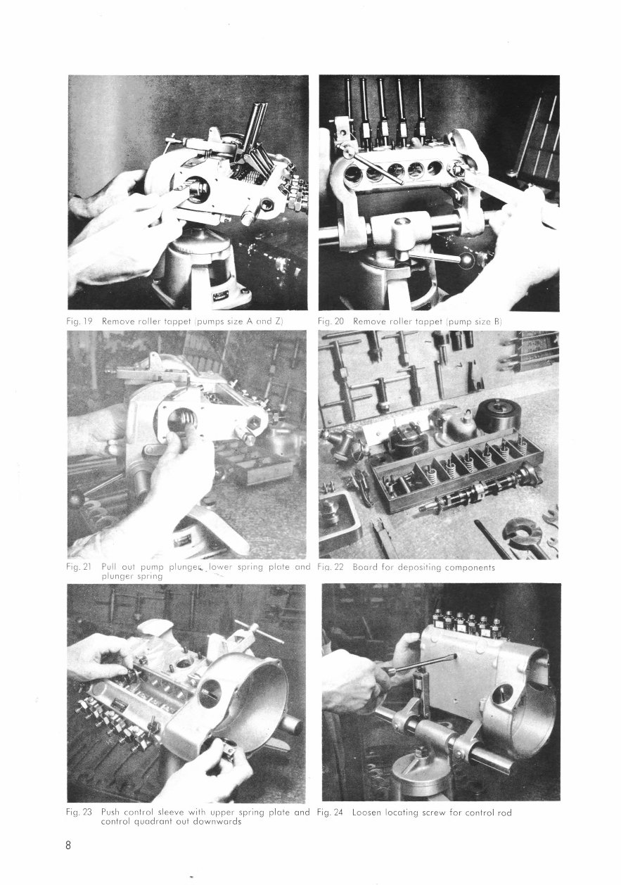
Fig. 20 Remove roller tappet pump size B) Fig. 19 Remove roller tappet .pumps size A and Z)
• •,.< .
„ -
4
„
Fig. 21 Pull out pump plungec . lower spring plate and Fia. 22 Board for depositing components
plunger spring
Fig. 23 Push control sleeve with upper spring plate and Fig. 24 Loosen locating screw for control rod
control quadrant out downwards
8
You're Reading a Preview
What's Included?
Fast Download Speeds
Online & Offline Access
Access PDF Contents & Bookmarks
Full Search Facility
Print one or all pages of your manual
$31.99
Viewed 33 Times Today


Secure transaction
What's Included?
Fast Download Speeds
Online & Offline Access
Access PDF Contents & Bookmarks
Full Search Facility
Print one or all pages of your manual
$31.99
These digital manuals provide comprehensive guidance for car repair, catering to the needs of both professional mechanics and DIY enthusiasts. The manuals cover a wide range of topics, including initial examination, dismantling, repair and replacement, assembly, special tools and appliances, tightening torques, and explanation of injection pump marks.
- Introduction
- Initial Examination
- Without pump being removed
- With pump removed
- Dismantling
- Sequence of Operations on Pumps Type PE
- Sequence of Operations on Pumps Type PF
- Repair and Replacement
- Elements
- Delivery Valve
- Roller Tappet or Plunger Guide
- Camshaft
- Ball Bearings
- Control Rod
- Control Quadrant and Sleeve
- Plunger Spring
- Pump Housing
- Assembly
- Assembly Numbers
- Sequence of Operations for Assembly
- Special Tools and Appliances
- Tightening Torques
- Explanation of Injection Pump Marks
These manuals are available in .PDF format, providing valuable insights and instructions for efficient car repair and maintenance.


