Service Manual Wartungshandbuch Manuel de maintenance RT3020 Serie
Printed in Germany TABLE OF CONTENT
Printed in Germany Page intentionally left blank Seite absichtlich freigelassen Page intentionellement laissée blanche
Printed in Germany M-IDX-2900-001 TABLE OF CONTENT Table of Content MA – SAFETY PAGE SER-NR. CUT REV. Safety Symbols used in the Manual .................................. M/P-MA-0000-001 General Maintenance and Repair Safety Notes ............... M/P-MA-0000-001 - Maintenance and Repair ................................................. M/P-MA-0000-002 - Before Leaving the Truck ................................................. M/P-MA-0000-002 - Before Carrying out Work on the Truck ............................ M/P-MA-0000-002 - Before Operating the Truck .............................................. M/P-MA-0000-002 Warnings and Labels on the Truck .................................... M/P-MA-0000-002 ITD – INTRODUCTION PAGE SER-NR. CUT REV. General ................................................................................. M/P-ITD-2900-001 - Operating instruction ....................................................... M/P-ITD-2900-001 - Service training ............................................................... M/P-ITD-2900-001 - Replacement parts orders ............................................... M/P-ITD-2900-001 - Structure of the Manual .................................................. M/P-ITD-2900-001 - Page Numbers ................................................................ M/P-ITD-2900-002 Truck Data Numbering Sheet ............................................... M/P-ITD-2900-004 M1 – LUBRICATION AND ADJUSTMENT PAGE SER-NR. CUT REV. Jacking up the Truck ............................................................ M-1.0-2900-001 Raising the Truck with a Crane ............................................ M-1.0-2900-002 Lifting the Truck with a second Truck ................................. M-1.0-2900-002 Towing the Truck .................................................................. M-1.0-2900-002 Component Access .............................................................. M-1.0-2900-003 Removing the Floorboard .................................................. M-1.0-2900-005 Removing the Side Panel .................................................. M-1.0-2900-005 Access to Drive Unit, Hydraulic System and Electrical Components ............................................... M-1.0-2900-005 Maintenance ......................................................................... M-1.1-2900-001 - Driver Participation ......................................................... M-1.1-2900-001 - Daily Maintenance Log .................................................... M-1.1-2900-001 - Recommended Lubricants and Oils ................................ M-1.1-2900-001 - Lubricants .................................................................. M-1.1-2900-002 Grease items and grease intervals .................................... M-1.2-2900-002 - Inspection and Maintenance Schedule ............................ M-1.2-2900-002 - Daily or every 8 service hours ................................... M-1.2-2900-003 - Monthly or every 100 service hours ........................... M-1.2-2900-005 - Every three months or 250 service hours ................... M-1.2-2900-007 - Every six months or 500 service hours ...................... M-1.2-2900-009 - Annually or every 1.000 service hours ....................... M-1.2-2900-011 - Every 2 years or 2.000 service hours ........................ M-1.2-2900-011 Caster .................................................................................... M-1.5-2900-001 Torques ................................................................................. M-1.9-2900-002 M2 – HYDRAULICS PAGE SER-NR. CUT REV. Hydraulic System ................................................................. M/P-M2.1-2900-001 Operation .......................................................................... M/P-M2.1-2900-001 Removing the Hydraulic Unit ............................................. M-2.2-2900-001 Replacing the Hydraulic Pump .......................................... M-2.3-2900-001 - Disassembly .............................................................. M-2.3-2900-001 - Assembly .................................................................. M-2.3-2900-001 - Start-up ..................................................................... M-2.3-2900-001 Replacing the Hydraulic Filter ........................................... M-2.3-2900-001 - Replacing the Suction Filter ....................................... M-2.3-2900-001 - Oil Change ................................................................. M-2.3-2900-002
Printed in Germany M-IDX-2900-002 TABLE OF CONTENT Valve Setting Control ........................................................ M-2.3-2900-004 Non-return valve control ............................................... M-2.3-2900-004 Safety Valve Control .................................................... M-2.3-2900-004 Safety Valve Setting .................................................... M-2.3-2900-004 M3 – DRIVE UNIT PAGE SER-NR. CUT REV. Gear Unit ............................................................................... M-3.1-2900-001 Preparation ....................................................................... M-3.1-2900-001 Maintenance ..................................................................... M-3.1-2900-002 - General ...................................................................... M-3.1-2900-002 Drive Unit Disassembly ..................................................... M-3.1-2900-003 Assembly .................................................................... M-3.1-2900-003 Adjusting the Bevel Wheel Set ..................................... M-3.1-2900-004 Final Assembly ............................................................ M-3.1-2900-004 Drive Unit Re-Installation ............................................. M-3.1-2900-005 Live Ring Bearing Replacement ........................................ M-3.1-2900-005 Forcing out the Live Ring Bearing ................................ M-3.1-2900-005 Pressing in the Live Ring Bearing ................................ M-3.1-2900-005 Installation of the Live Ring Bearing in the Drive Unit ... M-3.1-2900-005 M4 – ELECTRICS PAGE SER-NR. CUT REV. Electrical Components ........................................................ M-4.2-2900-001 Transmitter (MC,MN,PT) ................................................... M-4.2-2900-001 Fast / Slow Switch (HES) .................................................. M-4.2-2900-001 Safety Pedal (PCT) ........................................................... M-4.2-2900-001 Lift / Lower Switch (PCS, PCD) ......................................... M-4.2-2900-001 Lift Limit Switch (MFF) ...................................................... M-4.2-2900-001 Pressure Switch (PS) ........................................................ M-4.2-2900-001 Horn Switch (PCX) ............................................................ M-4.2-2900-001 Horn (CX) .......................................................................... M-4.2-2900-001 Key Switch (QC) ............................................................... M-4.2-2900-001 Emergency Disconnect Switch (PE) ................................. M-4.2-2900-001 Steering Angle-Dependent Speed Reduction Microswitch . M-4.2-2900-001 Brake (FE) ........................................................................ M-4.2-2900-002 Fuses (F1, F2, FA) ............................................................ M-4.2-2900-002 Traction Motor (M1) ........................................................... M-4.2-2900-002 Pump Motor (M2) .............................................................. M-4.2-2900-002 Pump Contactor (K3) ........................................................ M-4.2-2900-002 Main Contactor (K4) .......................................................... M-4.2-2900-002 Raise Contactor (RLS) and Lower Contactor (RLD) ........... M-4.2-2900-002 OPTION Steering Motor (M3) .................................................... M-4.2-2900-002 OPTION Encoder (MS) ............................................................. M-4.2-2900-002 OPTION Limit Switch (MF) ....................................................... M-4.2-2900-002 OPTION Steering-Contactor (K6) .............................................. M-4.2-2900-002 OPTION Fuses (F3, FA3) ......................................................... M-4.2-2900-002 Travel Direction Display ..................................................... M-4.2-2900-002 ES1 Traction Controller ........................................................ M-4.3-2900-001 General ............................................................................. M-4.3-2900-001 - Precautionary Measures ............................................ M-4.3-2900-001 Operational Features ......................................................... M-4.3-2900-001 - Speed Control ............................................................ M-4.3-2900-001 - Reduced Speed Range .............................................. M-4.3-2900-001 - Downhill Speed Control .............................................. M-4.3-2900-001 - Regenerative Braking ................................................. M-4.3-2900-001 - Anti-Roll-Down-Function ............................................. M-4.3-2900-001
Printed in Germany M-IDX-2900-003 TABLE OF CONTENT - Hourmeter .................................................................. M-4.3-2900-002 Self Test ....................................................................... M-4.3-2900-002 - Monitored Circuits ...................................................... M-4.3-2900-002 Protective Devices ............................................................ M-4.3-2900-003 - Polarity Protection ..................................................... M-4.3-2900-003 - Wiring Errors .............................................................. M-4.3-2900-003 - Temperature ............................................................... M-4.3-2900-003 - Start Sequence ......................................................... M-4.3-2900-003 - Safety Class .............................................................. M-4.3-2900-003 Maintenance ..................................................................... M-4.3-2900-003 ES1 Traction Controller Connections ................................. M-4.3-2900-004 Programmer ......................................................................... M-4.4-2900-001 General ............................................................................. M-4.4-2900-001 Operating Menu ES1 Controller ......................................... M-4.4-2900-002 - General ...................................................................... M-4.4-2900-002 - Menu Functions ......................................................... M-4.4-2900-002 - Operating Menu - Overview ....................................... M-4.4-2900-003 Adjustment ....................................................................... M-4.5-2900-001 - Menu PARAMETER CHANGE ................................... M-4.5-2900-001 - Max. Speed Setting ................................................... M-4.5-2900-002 - TESTER Menu ........................................................... M-4.5-2900-004 - Error Code Display in SAM Hourmeter ....................... M-4.5-2900-006 - ALARMS Menu .......................................................... M-4.5-2900-006 - PROGRAM VACC Menu ............................................ M-4.5-2900-009 CONFIG Menu ............................................................. M-4.5-2900-010 SAM Hourmeter ................................................................ M-4.5-2900-01 Traction Controller Replacement and Transfer of Service Hours into the new Controller: ......................... M-4.5-2900-011 Traction Controller Safety Test ............................................ M-4.20-2900-001 Battery ................................................................................... M-4.25-2900-001 General ............................................................................. M-4.25-2900-001 Operation .......................................................................... M-4.25-2900-001 Battery Replacement ........................................................ M-4.25-2900-001 Battery Removal ............................................................... M-4.25-2900-001 - Replacing the Battery with a Crane ............................ M-4.25-2900-002 - Replacing the Battery with a Battery Trolley ............... M-4.25-2900-003 Charging the Battery .................................................... M-4.25-2900-004 Electric Motors ..................................................................... M-4.35-2900-001 General Maintenance Instructions ..................................... M-4.35-2900-001 Preparation .................................................................. M-4.35-2900-001 Important Maintenance Instructions ............................. M-4.35-2900-001 Traction Motor Maintenance ................................................ M-4.35-2900-002 Access to the Brushes ..................................................... M-4.35-2900-002 Maintenance ..................................................................... M-4.35-2900-002 - Armature .................................................................... M-4.35-2900-002 - Bearings .................................................................... M-4.35-2900-002 Pump Motor Maintenance ................................................... M-4.35-2900-003 Access to the Brushes ..................................................... M-4.35-2900-003 Maintenance ..................................................................... M-4.35-2900-003 OPTION Steering Motor Maintenance ......................................... M-4.35-2900-004 Access to the Brushes ..................................................... M-4.35-2900-004 Maintenance ..................................................................... M-4.35-2900-004
Printed in Germany M-IDX-2900-004 TABLE OF CONTENT M-5 – BRAKE PAGE SER-NR. CUT REV. Brake ..................................................................................... M-5.0-2900-001 - Function ......................................................................... M-5.0-2900-001 - Removal ......................................................................... M-5.0-2900-001 - Assembly ....................................................................... M-5.0-2900-002 - Air Gap Setting ............................................................... M-5.0-2900-002 - Brake Moment Setting .................................................... M-5.0-2900-002 - Brake Test ....................................................................... M-5.0-2900-003 M6 – STEERING PAGE SER-NR. CUT REV. Steering ................................................................................ M-6.1-2900-001 Operation .......................................................................... M-6.1-2900-001 Lower Steering Chain Adjustment ..................................... M-6.1-2900-002 Adjusting the Drive Unit Steering Chain ............................ M-6.1-2900-002 Checking the Sliding Clutch .............................................. M-6.1-2900-003 Replacing the Sliding Clutch ............................................. M-6.1-2900-003 OPTION Steering Sensor Removal / Installation ...................... M-6.1-2900-004 OPTION Steering Motor Removal / Installation ........................ M-6.1-2900-004 OPTION Limit Switch Removal / Installation ........................... M-6.1-2900-004 M7 – LIFTING MECHANISM PAGE SER-NR. CUT REV. Lifting Mechanism ............................................................... M-7.0-2900-001 Test ................................................................................... M-7.0-2900-001 Adjusting the Stop ............................................................ M-7.0-2900-001 M8 – CYLINDERS PAGE SER-NR. CUT REV. Cylinders .............................................................................. M-8.0-0000-001 General ............................................................................. M-8.0-0000-001 Plunger Cylinders (single-acting) .................................. M-8.0-0000-001 Piston Cylinder (Double-Acting Cylinder) ...................... M-8.0-0000-002 Maintenance ..................................................................... M-8.0-0000-004 Inspection ......................................................................... M-8.0-0000-001 Seal Installation ................................................................... M-8.6-2900-001 General ............................................................................. M-8.6-2900-001 Lift Cylinder ....................................................................... M-8.6-2900-001 Removal Preparation ......................................................... M-8.6-2900-001 Removal ........................................................................... M-8.6-2900-001 Repairing the Lift Cylinder ................................................. M-8.6-2900-002 - Disassembly .............................................................. M-8.6-2900-002 - Inspection .................................................................. M-8.6-2900-002 - Assembly .................................................................. M-8.6-2900-002 Assembly ......................................................................... M-8.6-2900-002 Gas Pressure Spring Removal and Assembly ................... M-8.6-2900-003 - Removal Preparation ................................................. M-8.6-2900-003 - Removal .................................................................... M-8.6-2900-003 - Assembly .................................................................. M-8.6-2900-003 DIA – ELECTRICAL DIAGRAMS PAGE SER-NR. CUT REV. Standard Version .................................................................. M/P-DIA-2900-001 OPTION With electrical steering .................................................. M/P-DIA-2900-002 HYD – HYDRAULIC SCHEMATIC PAGE SER-NR. CUT REV. Hydraulic Schematic ......................................................... M/P-HYD-2900-001
Printed in Germany SAFETY
Printed in Germany Page intentionally left blank Seite absichtlich freigelassen Page intentionellement laissée blanche
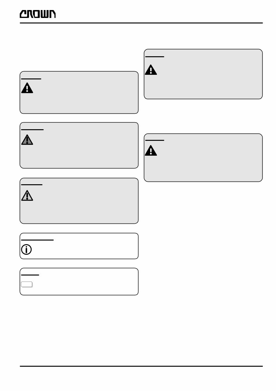
Printed in Germany 1 M/P-MA-0000-001 SAFETY REV. 1 4/00 OPTION Safety Symbols used in the Manual To help guide you through the manual and to highlight particular danger areas, we have used graphic illustra- tions: DANGER This symbol indicates life-threatening risks ● Failure to comply with this notice may result in severe or fatal injuries to yourself or other people. WARNING This symbol indicates the risk of serious injury and/or serious material damage. ● Failure to comply with this notice may result in severe injuries to yourself or other people and/or serious material damage. CAUTION This symbol indicates the risk of minor injury and/or minor material damage. ● Failure to comply with this notice may result in minor injuries to yourself or other people and/or minor material damage. INFORMATION Contains additional information with supplementary notes and hints. OPTION These items relate to optional features not supplied with the standard version. General Maintenance and Repair Safety Notes DANGER Read the safety notices in the truck Mainte- nance and Operator's Manuals. ● Failure to do so could result in severe or fatal injuries to maintenance personnel and/or other persons. Motorised vehicles can be dangerous if maintenance and service are neglected. For this reason maintenance and inspections must be carried out at regular short intervals by trained personnel working to approved company guidelines. DANGER Follow all national/local safety regulations applicable for maintenance work, e.g. for work on higher levels. ● Failure to do so could result in severe or fatal injuries to maintenance personnel and/ or other persons. Maintenance and Repair 1. Maintenance work must only be carried out in accordance with the test and maintenance pro- gram contained in the present Maintenance Manual and any applicable service notices. 2. Only qualified and authorised personnel may carry out work on the truck. 3. Always keep fire extinguishers in good working condition. Do not approach fluid levels or leaks with a naked flame. 4. To clean, use a non flammable, non combustible cleaning solution which is groundwater-neutral. Only carry out cleaning with an oil separator. Protect the electrical system from dampness. 5. Keep the service area clean, dry and well-venti- lated. 6. Do not allow oil to penetrate the ground or enter the draining system. Used oil must be recycled. Oil filters and desiccants must be treated as special waste products. Relevant applicable regulations must be followed. 7. Neutralise and thoroughly rinse any spilled battery fluid immediately.
You're Reading a Preview
What's Included?
Lifetime Access
Fast Download Speeds
Online & Offline Access
Access PDF Contents & Bookmarks
Full Search Facility
Print one or all pages of your manual
$41.99$54.99
Crown Forklift RT3020 Series Workshop Service Repair Manual (English French German)
This workshop service repair manual for the Crown Forklift RT3020 Series provides high-quality diagrams and instructions for servicing and repairing your forklift. It covers essential areas such as safety, introduction, lubrication and adjustment, hydraulics, drive unit, electrics, brake, steering, mast, wiring diagrams, and hydraulic diagrams.
Whether you are a professional mechanic or a DIY enthusiast, this manual is a valuable resource that can save you money on service repair and maintenance costs. It is instantly accessible upon payment, eliminating the need for shipping or waiting for a CD to arrive. The manual is compatible with all versions of Windows & Mac, as well as APP ISO, iPhone, iPod, Android, etc. It is presented in English and requires Adobe Reader for viewing and printing.
Get your hands on this practical service repair manual today and enhance your understanding of your Crown Forklift RT3020 Series.
Recently Viewed
5,521,897Happy Clients
2,594,462eManuals
1,120,453Trusted Sellers
15Years in Business
Price:
Actual Price:
Crown Forklift RT3020 Series Workshop Service Repair Manual (English French German)

")