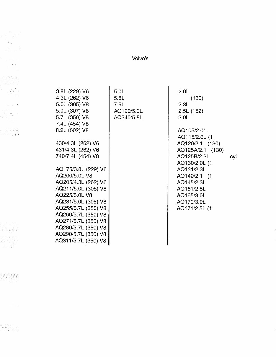
ENGINE FINDER The following listings contain all engines covered in this manual. Throughout the year cov- erage of this manual, Volvo Penta used engines manufactured by a number of different sup- pliers, hence we have categorized them by their manufacturer. We have also listed each engine by its size and configuration, and, Volvo's unique designation, if any. All versions of each engine are covered in the pages within, regardless of fuel, ignition or drive system. General Motors Ford 5.0L (302) V8 5.8L (351) V8 7.5L (460) V8 AQI 9015.OL (302) V8 AQ24015.8L (351) V8 Volvo 2.0L (121) 4 cyl 2.1L (1 30) 4 cyl 2.3L (141) 4 cyl 2.5L (1 52) 4 cyl 3.0L (182) 6 cyl AQI 0512.OL (121) 4 cyl AQI 1512.OL (1 21) 4 cyl AQ12012.1 L (1 30) 4 cyl AQ125Al2.1 L (1 30) 4 cyl AQ125B12.3L (141) 4 cyl AQ13012.OL (1 21 ) 4 cyl AQ13112.3L (141) 4 cyl AQI 4012.1 L (1 30) 4 cyl AQ14512.3L (141) 4 cyl AQ15112.5L (152) 4 cyl AQ16513.0L (182) 6 cyl AQ17013.OL (182) 6 cyl AQ17112.5L (1 52) 4 cyl
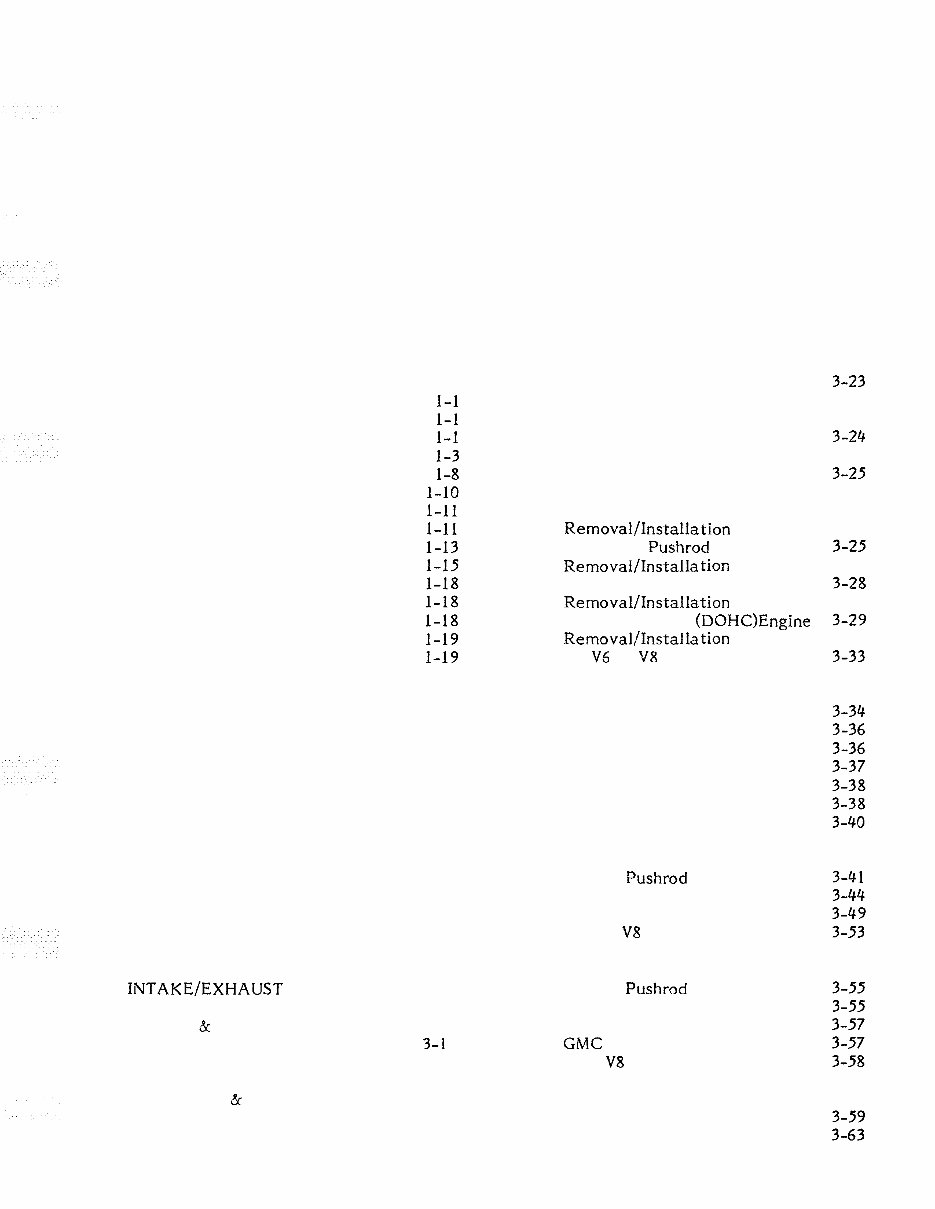
TABLE OF CONTENTS 1 SAFETY INTRODUCTION CLEANING, WAXING, POLISHING CONTROLLING CORROSION PROPELLERS FUEL SYSTEM LOADING HORSEPOWER FLOTATION EMERGENCY EQUIPMENT COMPASS POWER STEERING SYSTEM ANCHORS MISCELLANEOUS EQUIPMENT BOATING ACCIDENT REPORTS NAVIGATION 2 TUNING INTRODUCTION 2- 1 TUNING FOR PERFORMANCE 2-1 MECHANICAL TASKS 2-1 IGNITION 2- 5 FUEL SYSTEM 2-9 3 ENGINE GENERAL PRINCIPLES 3-1 CHAPTER ORGANIZATION 3-3 TROUBLESHOOTING CHECK 3-4 ENGINE REMOVAL 3-8 ENGINE INSTALLATION 3-12 INTAKE/EXHAUST MANIFOLD IN-LINE ENGINES 3 - 1 6 INTAKE & EXHAUST MANIFOLDS DOUBLE OHC (DOHC) ENGINE 3-1 7 Exhaust Manifold Removal 3-1 8 Intake Manifold Removal 3-19 Cleaning & Inspecting 3-20 Intake Installation 3-20 Exhaust Installation 3-21 INTAKE MANIFOLD V6 OR V8 ENGINE EXHAUST MANIFOLD V6 OR V8 ENGINE ROCKER ARM SERVICE CYLINDER HEAD RemovaI/Installation In- line Pushrod Engine Removal/Installa tion Single OHC Engine Removal/Instaflation Double OHC (D0HC)Engine Removal/Installa tion V6 or V8 Engine Head Reconditioning Disassembling Valve Guides Valve Springs Valves Hydraulic Lifters Valve Seats Head Assembling CAMSHAFT SERVICE In- Line Pushrod Engine Single OHC Engine Double OHC (DOHC) Engine V6 a n d V8 Engines VALVE LASH ADJUSTMENT In- Line Pushrod Engine Single OHC Engine Double OHC (DOHC) Engine GMC V6 and V8 Engines Ford V8 Engines TIMING BELT SERVICE Single OHC Engine Double QHC (DOHC) Engine
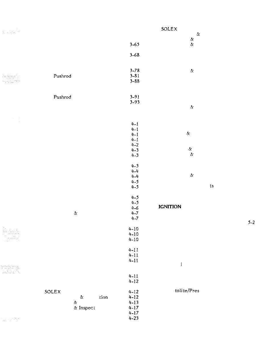
3 ENGINE (Continued) SOLEX SIDE- DRAFT 4-25 Description & Operation 4-25 Removal & Disassembling 4-25 Cleaning & Inspecting 4-28 Assembling 4-28 TIMING CHAIN SERVICE V6 and V8 Engines PISTON, RING, AND ROD SERVICE ROCHESTER 2GC 4-33 Disassembling 4-33 Cleaning & Inspecting 4-36 Assembling 4-36 Bench Adjustments 4-39 CRANKSHAFT AND MAIN BEARINGS Pushrod and OHC Engines V6 a n d V8 Engines OIL PUMP SERVICE Pushrod and OHC Engines V6 and V8 Engines ROCHESTER 4MV 4-41 Description 4-41 Disassembling 4-45 Cleaning & Inspecting 4-47 Bench Adjustments 4-51 4 FUEL INTRODUCTION Single Diaphragm Pump Dual - Diaphragm Pump TROUBLESHOOTING Rough Engine Idle Excessive Fuel Consumption Engine Surge FUEL LINE AND FUEL PUMP TESTS Fuel Line Test Fuel Pump Tests Pump Pressure Test Pump Volume Test HOLLEY CARBURETORS 2300 - TWO- BARREL 4150, 4160 & 4011 - FOUR- BARREL 4-55 Description 4-55 Disassembling -- Model 2300, 4150 & 4160 4-61 Cleaning & Inspecting 4-62 Assembling 4-64 Tuning Adjustments 4-67 Disassembling - Model 401 1 4-70 Cleaning & Inspecting 4-77 Assembling 4-79 Tuning Adjust men ts 4-86 CARBURETOR SPECIFICATIONS 4-90 VOLVO FUEL PUMP SERVICE Removal Disassembling Cleaning & Inspecting Assembling 5 IGNITION DESCRIPTION 5-1 Ballast Resistor 5-2 Ignition Timing 5-2 IGNITION TROUBLESHOOTING 5- 3 Compression 5- 3 System Tests 5-3 Voltage Tests 5-6 SPARK PLUG TROUBLESHOOTING 5-9 Evaluation 5-10 Polar i cy Check 5-12 DISTRIBUTOR SERVICE 5-12 DISTRIBUTOR REMOVAL 5-14 Bosch 5-14 Mallory 5-14 Au toli te/Pres toli te 5-14 CARTER FUEL PUMP SERVICE Removal Installation FUEL SYSTEM ACCESSORIES Fuel Filter Replacement Flame Arrester CARBURETORS Introduction "Sour" Fuel SOLEX DOWNDRAFT Description & Opera tion Removal & Disassembling Cleaning & Inspec t ing Assembling Adjustments BOSCH DISTRIBUTOR SERVICE 5-14 Disassembling 5-14 Cleaning and Inspecting 5- 16 Assembling 5- 17
5 IGNITION (Continued) MALLORY DISTRIBUTOR SERVICE 5-1 9 Removal & Disassembling 5- 19 Cleaning & Inspecting 5-1 9 Assembling 5-21 AUTOLITE/PRESTOLITE 5-22 Disassembling 5-22 Cleaning & Inspecting 5-23 Assembling 5- 25 ADJUSTING POINT GAP ALL DISTRIBUTORS 5- 25 DISTRIBUTOR INSTALLATION 5- 27 Adjusting the Dwell 5- 28 Adjusting Ignition Timing 5- 29 RENIX ELECTRONIC IGNITION SYSTEM -- MODEL AQ171 SERIES 5-30 Description & Operation 5-30 Checking Renix System 5-32 Troubleshooting Renix 5-32 STANDARD ELECTRONIC IGNITION SYSTEM -- Late Model V6 & V8 5- 35 Description Opera tion Troubleshooting 5 ELECTRICAL INTRODUCTION BATTERIES Construction Location Service Jumper Cables Storage Dual Battery Installa tion GAUGES AND LIGHTS Constant Voltage System Oil & Temp. Gauges Warning Lights Thermomel t Sticks Fuel Gauges Tachometer HORNS CHARGING SYSTEM A1 ternator -- Description and Operation Alternator Protection During Service Troubleshoo tin^ SERVICING CHARGING SYSTEM WITH SEPARATE REGULATOR PRESTOLITE 6-16 Disassembling 6- 16 Cleaning & Testing 6- 16 SERVICING CHARGING SYSTEM WITH INTEGRAL REGULATOR PRESTOLITE 6- 18 Disassembling 6- 19 Cleaning & Testing 6- 19 SERVICING CHARGING SYSTEM WITH SEPARATE REGULATOR SEV MARCHAL ALTERNATOR 6-21 Removal & Disassembling 6-21 Bench Testing 6-21 Assembling & Installation 6- 24 SERVICING CHARGING SYSTEM WITH INTEGRAL REGULATOR DELCOTRON 6- 25 Disassembling 6-26 Cleaning & Testing 6-26 SERVICING CHARGING SYSTEM WITH INTEGRAL REGULATOR MOTOROLA 6- 28 Disassembling 6-31 Cleaning & Testing 6-31 SERVICING CHARGING SYSTEM WITH INTEGRAL REGULATOR VALE0 6-34 Troubleshooting 6-34 Removal 6- 35 Cleaning & Testing Brushes 6- 36 Alternator Testing 6-36 Assembling & Installation 6- 39 CRANKING SYSTEM Troubleshooting AUTOLITE CRANKING MOTOR 6- 44 Disassembling 6-44 Cleaning & Inspecting 6- 45 Bench Testing 6- 45 Assembling 6- 47 PRESTOLITE CRANKING MOTOR 6- 48 Disassembling 6- 48 Cleaning & Inspecting 6- 49 Assembling 6-49 BOSCH CRANKING MOTOR 6- 51 Removal 6-51 Tests 6-52
6 ELECTRICAL (Continued) BOSCH CRANKING MTR. (Cont.) Disassembling Cleaning & Inspecting Assembling Testing Completed Work Installation DELCO CRANKING MOTOR Servicing & Testing Assembling 7 COOLING DESCRIPTION "RAW" WATER STRAINER HEATEXCHANGER "RAW" WATER PUMP THERMOSTAT OIL COOLER 8 STERN DRIVE INTRODUCTION Opera tion TROUBLESHOOTING Stern Drive Noises Service Precau tions PROPELLER SERVICE Removal " Frozen " Propeller Change Propeller Rota tion Retaining Pawl Adjustment Propeller Ins tallat ion STERN DRIVE Removal Installation UPPER GEAR ASSEMBLY Disassembling Cleaning & Inspecting Assembling INTER MEDIATE HOUSING Disassembling Cleaning & Inspecting Assembling STANDARD PROPELLER LOWER UNIT Preparation Disassembling Cleaning & Inspecting Assembling EXTENSIONS DUOPROP LOWER UNIT Propeller Set- vice Propeller Removal Propeller Installa tion Preparation for Service Disassembling Cleaning & Inspecting Assembling Shim Calculations Assembling Continues Checking Backlash INTRODUCTION Ti1 t Trim TROUBLESHOOTING TILT SYSTEM SERVICE Removal & Disassembling 9-4 Cleaning & Inspecting 9-9 Assembling & Installation 9-9 TRIM SYSTEM SERVICE Removal & Disassembling 9-13 Cleaning & Inspecting 9-14 Assernbling & Installation 9-15 TRIM SENDER SERVICE Replace Wire 9-16 10 STEERING DESCRIPTION 10- 1 SERVO VALVE ADJUSTMENT 10- 3 POWER STEERING COOLER 10-4 POWER STEERING KIT 10-4 11 MAINTENANCE IN-SEASON MAINTENANCE Before Starting - First Time Every 2 Weeks Every 50 Hours Every 100 Hours Retaining Pawl Adjustment OFF- SEASON STORAGE PRE- SEASON PREPARATION ADJUSTING BOAT TRIM ADJUSTING TRIM TAB FIBERGLASS HULLS BELOW WATERLINE SERVICE GIMBAL HOUSING -- EXPLODED DRAWING 11- 12
APPENDIX Engine AQ190A & 240A A- 49 METRIC CONVERSION CHART A-1 DRILL SIZE CONVERSION CHART A-2 REPLACEMENT PISTONS AQ125 AND AQ145 ENGINES A-3 VALVE ADJUSTING KIT AQ125 AND AQ145 ENGINES A-3 TUNE - UP ADJUSTMENTS A-4 Complete AQ205, A921 1 A, AQ23 1, AQ271C & AQ311A & B A-50 Model 431 A-5 1 Instrument Panel AQ200AB & AQ290A with ammeter A-52 ENGINE SPECIFICATIONS 4 - Cylinder OHC AQ120B, AQ125A, AQ140A, AND AQ145A A-8 Engine AQ200AB, AQ225AB, h AQ290A with ammeter A- 53 Instrument Panel AQ200AB, AQ225AB & AQ290A with voltmeter A-54 4 - Cylinder OHC & DOHC AQ125B, AQ131 A, AQ145B, AQ151 A, A N D AQ171A A-14 Engine AQ200AB, AQ225AB & AQ290A with voltmeter A- 55 4- & 6 - Cylinder In- Line AQ105A, AQ115A, AQ130A, B, C & D, AQ165A, and AQ170A, B & C A-20 Complete AQ200C, AQ225C, & AQ225A with ammeter A-56 GMC V6 AQ175A A-25 Complete AQ200C AQ225C, & AQ225A with voltmeter A- 57 GMC V6 Model 431 A- 28 GMC V6 305CID, 307CID, 350CID & 454CID A-32 Instrument Panel AQ280A & AQ225A A-58 Engine AQ280A & AQ225A A- 59 Ford V8 AQ190A & AQ240A A- 37 Complete Model 740 A-60 HOLLEY CARBURETOR SPECS. A-41 Instrument Panel with ammeter and with voltmeter -- AQ200D, AQ225D, AQ260A & D, AQ290A, and all other CMC V6, V8, and Ford V8 A- 6 1 TORQUE SPECS. AQI 9OA AND AQ240A A-41 WIRE IDENTIFICATION DWGS. AQlOSA, AQ115A, AQ130A, B, C, & D, AQ165A, & AQ170A A-42 Power Tilt - - USA A-62 Power Tilt - - all except USA A- 63 Complete AQ120B, AQ125A & B, AQ140A, AQ145A & B A-43 Power Trim -- Single Station with trim gauge and trim limit switch A-64 Complete AQ131A, AQ151A & B A-44 Power Trim -- Dual Station with trim gauge and trim limit switch A-65 Complete AQ171A A- 45 Complete AQ175A A-46 Power Trim -- Late Type -- Single Station with trim gauge and trim limit switch A-66 Early Model AQ200D, AQ225D, AND AQ255D A-47 Instrument Panel AQl9OA & AQ240A with voltmeter A- 48
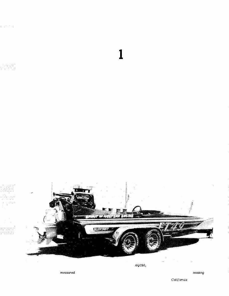
SAFETY 1 - 1 INTRODUCTION Your boat probably represents a sizeable investment for you. In order to protect this investment and to receive the maximum amount of enjoyment from your boat it must be cared for properly while being used and when it is out of the water. Always store your boat with the bow higher than the stern and be sure to remove the transom drain plug and the inner hull drain plugs. If you use any type of cover to protect your boat, plastic, canvas, whatever, be sure to allow for some movement of air through the hull. Proper ventilation will assure evaporation of any condensation that may form due to changes in temperature and humidity. 1 - 2 CLEANING, WAXING, AND POLISHING Any boat should be washed with clear water after each use to remove surface dirt and any salt deposits from use in salt water. Regular rinsing will extend the time be - tween waxing and polishing. It will also give you " pride of ownership" , by having a sharp looking piece of equipment. Elbow grease, a mild detergent, and a brush will be required to remove stubborn dirt, oil, and other un- sightly deposits. Stay away from harsh abrasives or strong chemical cleaners. A white buffing com- pound can be used to restore the original gloss to a scratched, dull, or faded area. The finish of your boat should be thoroughly cleaned, buffed, and polished at least once The Spirit of Western Engine, powered by a modified Volvo Penta AQ290, 350 CID engine and equipped with a Volvo stock Model 280 stern drive, attained 110 mph, when driven by Mike Basso during endurance competition. The boat was clocked by radar on a measured course. The only change to the lower unit was slight streamlining to the leading edge. Safety is a prime consideration for racing teams competing in such high-performance events. The " Spirit n is owned by Western Engine Distributors, Santa Ana, California, Volvo Penta distributors for Southern Califorrcia and neighboring areas until mid 1987, when Volvo eliminated the "three tier" distribution system.
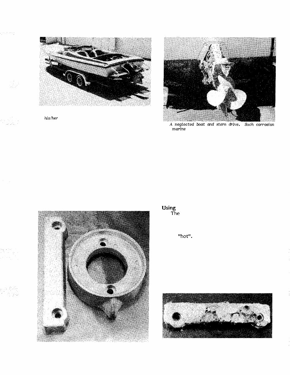
1 - 2 SAFETY Pride of Ownership This well-maintained boat, en- gine, stem drive, and trailer, reflect the owner's pride in hisher equipment. The rewards are efficiency, economy, enjoyment, and safe boating. each season. Take care when buffing or polishing with a marine cleaner not to over - heat the surface you are working, because you will burn it. 1-3 CONTROLLING CORROSION Since man first started out on the water, corrosion on his craft has been his enemy. The first form was merely rot in the wood and then it was rust, followed by other forms of destructive corrosion in the more modern materials. One defense against cor - rosion is to use similar metals throughout and ma&e growth will be costly to the owner and greatly reduce his boating enjoyment through poor per - formance. What a contrast with the equipment shown in the left column. the boat. Even though this is difficult to do in designing a new boat, particularly the undersides, similar metals should be used whenever and wherever possible. A second defense against corrosion is to insulate dissimilar metals. This can be done by using an exterior coating of Sea Skin or by insulating them with plastic or rubber gaskets. Using Zinc he proper amount of zinc attached to a boat is extremely important. The use of too much zinc can cause wood burning by plac - ing the metals close together and they be - come "hott'. On the other hand, using too small a zinc plate will cause more rapid deterioration of the metal you are trying to protect. If in doubt, consider the fact that it is far better to replace the zincs than to replace planking or other expensive metal parts from having an excess of zinc. Two proper size zincs may be purchased from the local Volvo Penta marine dealer, as shown in the accompanying illustration. A partially corroded zinc bar from the transom Zincs used with the Volvo Penta stern drive units. shield. An excellent example of how the inexpensive The bar attaches to the underside of the transom shield zincs are sacrificed to save more costly parts. The and the ring is secured to the bearing housing ahead of zincs should be checked regularly and changed when the propeller. they show this much deterioration.
Upon purchasing this manual, you will receive a .PDF file containing an email contact. After contacting us, you will receive a reply with a link to access the manual for your 1995 VOLVO PENTA 7.4GL INBOARD HS1.
This comprehensive manual covers every aspect of your machine, providing detailed guidance on every nut and bolt. With hundreds of pages, it offers instructions for tasks ranging from an oil change to a transmission swap, empowering both professional mechanics and DIY enthusiasts. The manual includes numerous illustrations to assist you and features easy-to-understand text.
Utilize the search function to navigate the manual efficiently and print the necessary pages. This Factory Service Repair Manual imparts fundamental maintenance and repair knowledge, guiding you through the process step by step. It equips you with the expertise that factory-trained technicians possess, enabling you to make informed decisions about maintaining and repairing your machine.
Rest assured, in addition to the high-quality service manual, we are committed to providing excellent customer service, ensuring your satisfaction.