

WISCONSIN V465D V460D V461D Engine Workshop Repair Manual
What's Included?
Fast Download Speeds
Online & Offline Access
Access PDF Contents & Bookmarks
Full Search Facility
Print one or all pages of your manual

WISCONSIN
MODELS V465D
V41NID, V461D
REPAIR
~
WISCONSIN
MOTORS, LLC
Downloaded from www.Manualslib.com manuals search engine
FOREWORD
Good operation and a planned maintenance program as outlined in this manual are vital in
obtaining maximum engine performance and long engine life. Theinstructions on the following
pages have been written with this in mind,to give the operatora better understanding of the
various problems which may arise, andthe manner in whichtheseproblems canbest be solved
or avoided.
Theoperatoris cautioned against the use of anyparts, other than genuine Wisconsin parts,
for replacement or repair. These parts have been engineered andtested for their particular
job, and the use of anyother parts may result in unsatisfactoryperformance and short engine
life. Wisconsin distributors and dealers, because of their close factory relations, canrender
the best and most efficient service.
THE LIFE OF YOUR ENGINE DEPENDS ON THE CARE IT RECEIVES.
The MODEL, SPECIFICATION and SERIAL NUMBER of your engine must be given when
ordering parts. The MODEL and SPECIFICATION number are on the name plate. The SERIAL
NUMBER is stamped either on the crankcase or the engine’s identification tag.
Copy the MODEL, SPECIFICATION and SERIAL NUMBER in the spaces provided below so
that it will be available when ordering parts.
MODEL
SPECIFICATION
SERIAL NUMBER
To insure prompt and accurate service, the following informationmust also be given:
1. State EXACTLY the quantity of eachpart andpart number.
2. State definitely whether parts are to be shipped by express, freight or parcel post.
3. State the exact mailing address.
Downloaded from www.Manualslib.com manuals search engine
IMPORTANT
READTHESE INSTRUCTIONSCAREFULLY
All pointsof operation and maintenance have been covered as carefully as possible, but if further
information is required, send inquiries to the factory for prompt attention.
When writing to the factory, ALWAYS GIVE THE MODEL, SPECIFICATION AND SERIAL
NUMBER of the enginereferred to.
Starting and Operatinq New Engines
Careful breaking-in of a new engine will greatly increase its life and result in troublefree operation.
A factory test is not sufficient to establish the polished bearing surfaces, which are so necessary
to the proper performance and long life of an engine. These canonly be obtained by running a
new engine carefully and under reduced loads for a short time.
¯ Be sure the engine is filled to the proper level with a good quality engine oil.
¯ For proper procedures to follow when breaking-in a new engine, see’Testing Rebuilt Engine’.
The various bearing surfaces in a new engine have not been glazed, as theywill be with continued
operation, and it is in this period of "running in" that specialcaremust be exercised, otherwise
the highly desired glaze will neverbe obtained. A new bearing surface that has once been
damaged by carelessness will be ruined forever.
Downloaded from www.Manualslib.com manuals search engine
IMPORTANT SAFETY NOTICE
Proper repair is important to the safe and reliable operation of an engine. This Repair Manual
outlines basic recommended procedures, some of whichrequire special tools, devices or work
methods.
Improper repair procedures can be dangerous andcould result in injury or death.
READ AND UNDERSTAND ALL SAFETY PRECAUTIONS AND
WARNINGS BEFORE PERFORMING REPAIRS ON THIS ENGINE
Warning labels have also been put on the engines to provide instructions and identify specific
hazards which, if not heeded, couldcause bodily injury or deathto youor other persons. These
labels identify hazards which may not be apparentto a trained mechanic. There are many
potential hazards for an untrained mechanic and there is no way to label the engine against all
suchhazards. These warnings in the RepairManual andon the engine are indentified by this
symbol:
z WARNING
Operations that may result only in engine damage are identified in the Repair Manual by this
symbol:
,&CAUTION
Wisconsin Motors, LLC cannotanticipate every possible circumstance that might involve a
potential hazard; therefore, the warnings in this manual are not all inclusive. If a procedure,
tool, deviceor workmethod not specifically recommended by Wisconsin Motors, LLC,is used,
youmust satisfy yourself that it is safe for youandothers. You should also ensure that the
engine will not be damaged or made unsafe by the procedures you choose.
IMPORTANT: Theinformation,specificationsandillustrations in this manual are based
on informationthat was available at the time it was published.The specifications,
torques, pressures of operation, measurements, adjustments, illustrations and other
items can change at any time. These changes can affect the service given to the
product. Get the complete and most current informationbefore starting any job. For
parts, service, or information, contact Wisconsin Motors,LLC, Memphis, Tennessee.
Downloaded from www.Manualslib.com manuals search engine
WARNING
Most sub-systems used in conjunction with Wisconsin Motors, LLC, industrial engines
including (but not limited to) radiators, hoses,fans, fuel tanks, fuel lines or other fuel system
components, batteries, electrical connections or other electrical components, clutches,
transmissions, hydraulic pumps and generators, are not supplied by Wisconsin Motors, LLC.
these items are provided by the manufacturer of the end item in which the engine is used.
Some of the dangers associated ’with servicing such items are generally mentioned in this
manual;however, the appropriate handbooks and safety instructions provided by the manufac-
turer of the enditem should always be consulted prior to the undertaking of any work on sub-
systems attached to the engine, to avoid any hazardsinherent to these sub-systems.
Read andobserve all individual safety warnings as you use this manual to operate, service or
repair your engine.
Alwaysexercise caution wheneve=" working with an engine or any associated system.
Injuries may be caused by lack of care when working with, or near, moving parts, hot parts,
pressurizedsystems,electrical equipment, or fuel systems.
Always wear eye and hearing protection when working on or near engines.
Improper attire such as looseclothing, ties, rings, soft shoes or bare feet couldbe hazardous and
should be avoided when servicing engines.
Use or service of the engine (including the useof modifiedparts or materials) not in accordance
with manufacturer’sspecifications could damage your engine or causepersonal injury.
WARNING
Some equipment and materials used in the overhaul or maintenance of an engine such as
machine tools, electrical equipment, compressed air, solvents, gasoline or other fuels may be
dangerous and can causeinjury. Alwaysobservesafety precautions.
iii
Downloaded from www.Manualslib.com manuals search engine
SAFETY PRECAUTIONS
¯
Never fill fuel tank while engne is running or hot;
avoid the possibility of spilled fuel causing a fire.
¯ Always refuel slowly to avoid spillage.
¯
When starting engine, maintain a safe distance
from moving parts of equipment.
¯ Donot start enginewith clutch engaged.
¯
Do not spin hand crank when starting. Keep
cranking components clean andfree from conditions
which might causethe crank jaw to bind and not
release properly.Oil periodically to prevent rust.
¯
Neverrun engine with governordisconnected,or
operate at speeds in excess of 2400 R.P.M. load.
Donot operateenginein a closed building unless
the exhaust is pipedoutside. This exhaust contains
carbon monoxide, a poisonous, odorless and
invisible gas, which if breathed causes serious
illness andpossible death.
Nevermake adjustments on machinery while it is
connected to the engine,without first removing the
ignition cable fromthe spark plug. Turning the
machineryover by hand during adjusting or
cleaningmight start the engine and machinery with
it, causing seriousinjury to the operator.
Precaution is the best insurance against
accidents.
Keep this book handy at all times,
familiarize yourself with the operating instructions.
Model V465D
3-3/4" Bore m 4" Stroke
177 cu. in. Displacement
Models V461 D, V460D
3-1/2" Bore- 4" Stroke
154 cu. in. Displacement
2
Downloaded from www.Manualslib.com manuals search engine
CONTENTS
Air Cleaner, Pre-Cleaner ....................................................... 11,12
Alternator -- Belt Driven .......................................................... 34
Bearing -- Center Main ............................................................. 11
Breather Cap .............................................................................. 10
Carburetor Adjustment ..............................................................
12
Carburetor Service
Zenith Model 87A8 ........................................................ 35-37
Clutch Adjustment .....................................................................
18
Clutch Power Take-off ............................................................... 18
Clutch Reduction Unit ................................................................ 19
Compression -- Restoring .......................................................... 16
Cooling ......................................................................................... 8
Dieseling, Anti-Diesel Valve ..................................................... 10
Disassembly and Reassembly ....................................................
23
Accessories .......................................................................... 23
Camshaft ..............................................................................
30
Camshaft Gear ..................................................................... 30
Carburetor and Manifold .....................................................
25
CenterMain Bearing, Roller Type (Older Models) .............. 32
Center Main Bearing, Shell Type ......................................... 30
Connecting Rod and Piston .................................................. 28
Crankshaft and Main Bearing Plate.....................................
31
Cylinder Barrel .................................................................... 27
Cylinder Head ...................................................................... 27
Cylinder Shrouding .............................................................. 25
Distributor and Accessory Drive .......................................... 24
Engine Supports and Oil Pan ...............................................
26
Flywheel ..............................................................................
23
Flywheel Shroud ..................................................................
24
Fuel Pump ............................................................................
25
Gear Cover ..........................................................................
25
Gear Train ............................................................................ 26
Generator ............................................................................. 24
Governor ...............................................................................
25
Oil Pressure Reducing Valve ............................................... 32
Oil Pressure Relief Valve ......................................................
31
Oil Pump ..............................................................................
26
Idler Gear and Shaft .............................................................. 31
Piston ................................................................................... 28
Piston Ring and Rod Clearance Chart ..................................
29
Piston Rings ......................................................................... 28
Valve Guides and Seat Inserts .............................................
30
Valves ..................................................................................
29
Rocker Arm Assembly ........................................................
30
Distributor Maintenance ............................................................
14
Electric Wiring Circuits .............................................................
15
Electrical Wiring Diagrams
Distributor Ignition with Alternator ..................................... 34
Distributor Ignition withGenerator (Older Models) ............ 14
Magneto Ignition ................................................................. 15
Firing Order ...............................................................................
12
Fuel .............................................................................................. 9
Fuel Mixture .............................................................................. 20
Fuel Pump and Priming ............................................................... 9
Gasoline Strainer ....................................................................... 12
General Information and Design ..................................................
8
Generator (Older Models) ..........................................................
15
Governor Adjustment and Operation .........................................
17
Horsepower .................................................................................
8
Ignition Spark ............................................................................ 16
Ignition System ..........................................................................
12
Illustrations, Engine
Take-off View .......................................................................
5
Fan End View ........................................................................
5
Sectional Views ..................................................................
6,7
Lubrication System .............................................................. 11
Keep Engine Clean ......................................................................
3
Lubrication ..................................................................................
8
Lubrication System ................................................................. 8,11
MagnetoService
Fairbanks-Morse Type FM-X4B7D ..................................... 38
Oil Filter ....................................................................................
10
Oil -- Grade of and Service Classification ..................................
9
Oil Pressure and Adjustment ......................................................
10
Rotation ....................................................................................... 8
Rocker Arm Covers ...................................................................
17
Safety Notice .......................................................................... ii-iii
Safety Precautions ....................................................................... 2
Safety Switch -- High Temperature .......................................... 19
Solid State Ignition Distributors ...................................... 12, 3940
Spark Plugs ................................................................................ 16
Starting Motor -- Electric ........................................................... 9
Starting and Operating Instructions ..............................................
8
Starting and Operating New Engines ............................................ i
Starting Procedure .......................................................................
9
Stopping Engine -- Vapor Lock ................................................ 10
Storage of Engine for Winter ..................................................... 21
Testing Rebuilt Engine ..............................................................
23
Timing ....................................................................................... 12
Distributor Timing ............................................................... 13
Magneto Timing .................................................................. 15
Neon Lamp Timing ............................................................. 14
Timing Instructions .................................................................... 13
Timing Marks ............................................................................ 13
Troubles -- Causes and Remedies ............................................. 20
Backfiring Through Carburetor ............................................ 21
Compression ........................................................................ 20
Engine S tops ........................................................................ 21
High Oil Pressure ................................................................. 21
Ignition ................................................................................ 20
Knocking ............................................................................. 21
Low or No Oil Pressure ....................................................... 21
Missing ................................................................................ 20
Overheating ......................................................................... 21
Starting Difficulties -- Fuel Mixture ...................................
20
Surging or Galloping ...........................................................
21
Valves -- Grinding ............................................................... 29,30
Valve Tappet Adjustment .......................................................... 16
Warm-Up Period -- Overspeeding ............................................ 10
Downloaded from www.Manualslib.com manuals search engine
KEEP EN( INE CLEAN
PREVENT OVERHEATING
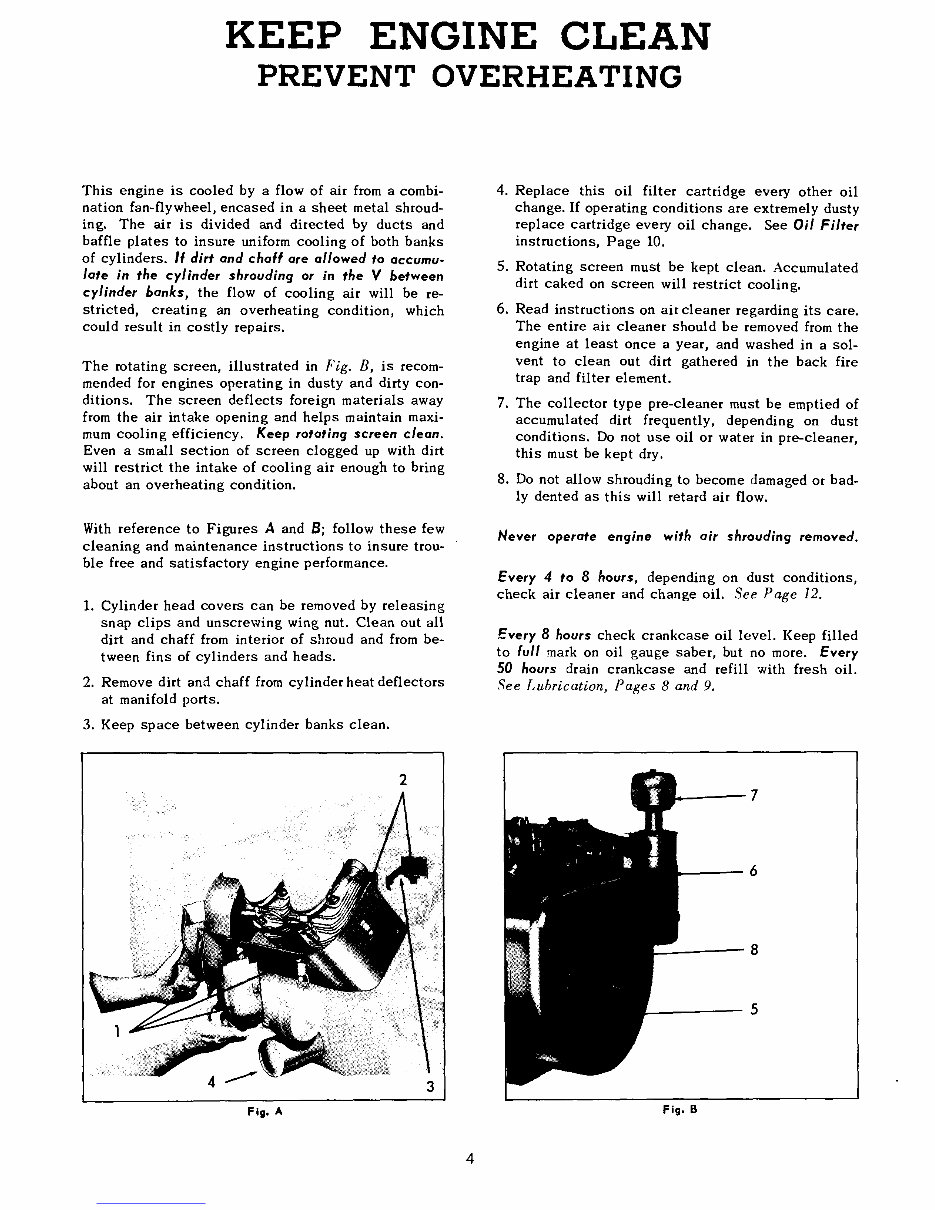
This engine is cooled by a flow of air from a combi-
nation fan-flywheel, encased in a sheet metal shroud-
ing. The air is divided and directed by ducts and
baffle plates to insure uniform cooling of both banks
of cylinders. If dirt and chaff are allowed to accumu-
late in the cylinder shrouding or in the V between
cylinder banks, the flow of cooling air will be re-
stricted, creating an overheating condition, which
could result in costly repairs.
The rotating screen, illustrated in Fig. B, is recom-
mended for engines operating in dusty and dirty con-
ditions. The screen deflects foreign materials away
from the air intake opening and helps maintain maxi-
mum cooling efficiency. Keep rotating screen clean.
Even a small section of screen clogged up with dirt
will restrict the intake of cooling air enough to bring
about an overheating condition.
With reference to Figures A and B; follow these few
cleaning and maintenance instructions to insure trou- ’
ble free and satisfactory engine performance.
1.
Cylinder head covers can be removed by releasing
snap clips and unscrewing wing nut. Clean out all
dirt and chaff from interior of shroud and from be-
tween fins of cylinders and heads.
2. Removedirt an,~ chaff from cylinder heat deflectors
at manifold ports.
3. Keep space between cylinder banks clean.
4. Replace this oil filter cartridge every other oil
change. If operating conditions are extremely dusty
replace cartridge every oil change. See Oil Filter
instructions, Page 10.
5. Rotating screen must be kept clean. Accumulated
dirt caked on screen will restrict cooling.
6. Read instructions on air cleaner regarding its care.
The entire air cleaner should be removed from the
engine at least once a year, and washed in a sol-
vent to clean out dirt gathered in the back fire
trap and filter element.
7. The collector type pre-cleaner must be emptied of
accumulated dirt frequently, depending on dust
conditions. Do not use oil or water in pre-cleaner,
this must be kept dry.
8.
Do not allow shrouding to become damaged or bad-
ly dented as this will retard air flow.
Never operate engine with air shrouding removed.
Every 4 to 8 hours, depending on dust conditions,
check air cleaner and change oil. See Page 12.
Every 8 hours check crankcase oil level. Keep filled
to full mark on oil gauge saber, but no more. Every
50 hours drain crankcase and refill with fresh oil.
See Lubrication, Pages 8 and 9.
4
Fig. A
6
Fig. B
Downloaded from www.Manualslib.com manuals search engine
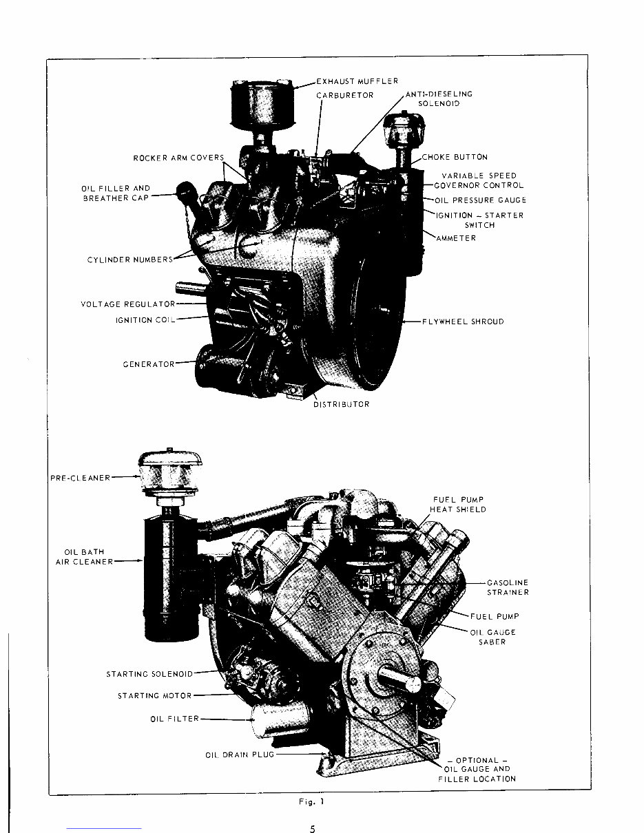
ROCKER ARM COVERS
OIL FILLER AND
BREATHER CAP
CYLINDER NU
VOLT AGE
IGNIT ION
GENE
PREoCLEANE
OIL BATH
AIR CLEANER
~
STARTING SO
STARTING MOTOR~
OIL FILTER
OIL DRAIN PLUG
MUFFLER
DISTRIBUTOR
ANTI-DIESE LING
SOLENOID
BUTTON
VARIABLE SPEED
~IOR CONTROL
PRESSURE GAUGE
- STARTER
SWITCH
fWHEEL SHROUD
FUEL PUMP
HEAT SHIELD
GASOLINE
STRAINER
PUMP
L GAUGE
SABER
-OPTIONAL-
OIL GAUGE AND
FILLER LOCATION
Fig. 1
Downloaded from www.Manualslib.com manuals search engine
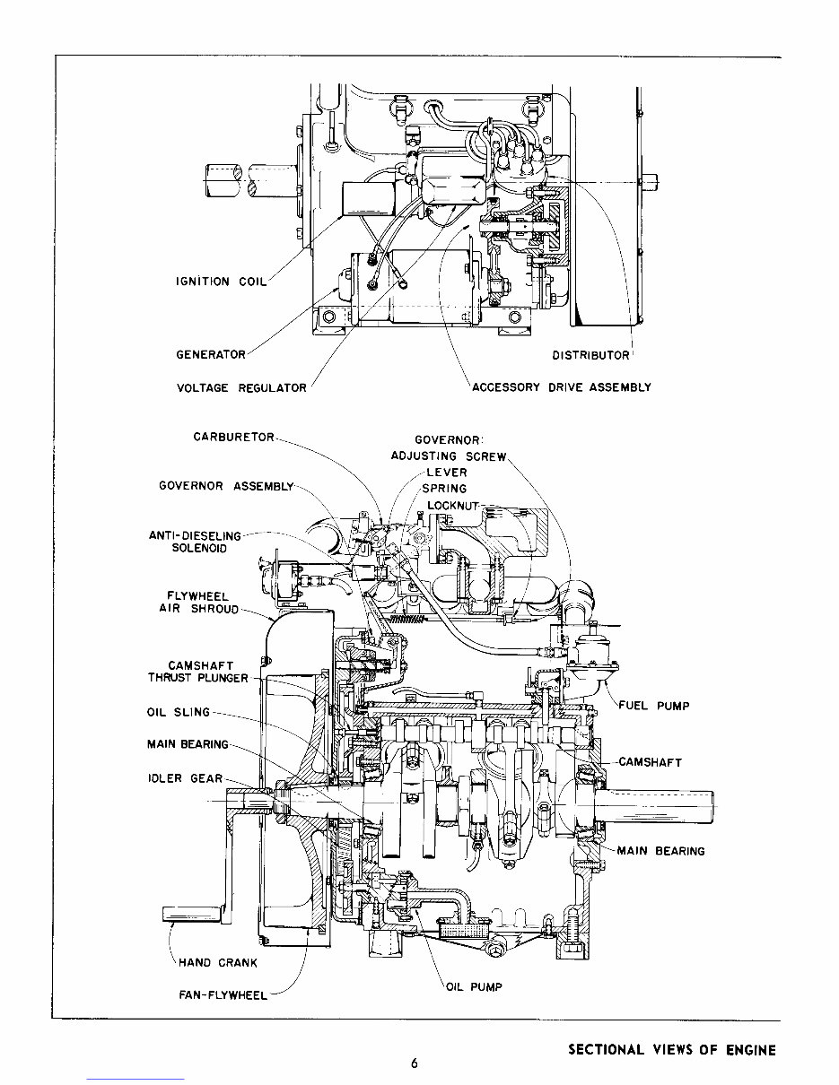
IGNITION COl.
GENERATOR
VOLTAGE REGULATOR
DISTRIBUTOR
;CESSORY DRIVE ASSEMBLY
CARBURETOR~
GOVERNOR ASSEMB~
ANTI-DIESELING~
SOLENOID
FLYWHEEL
AIR SHROUD
CAMSHAFT
THRUST PLUNGI
OIL
MAIN BEAI:
IDLER
GOVERNOR:
ADJUSTING SCREW
~LEVER ~
/SPRING
LOCKNUT~
I t.~,~_~
UEL PUMP
--CAMSHAFT
~-MAIN BEARING
HAND CRANK
FAN-FLYWHEEL
DIL PUMP
SECTIONAL VIEWS OF ENGINE
6
Downloaded from www.Manualslib.com manuals search engine
You're Reading a Preview
What's Included?
Fast Download Speeds
Online & Offline Access
Access PDF Contents & Bookmarks
Full Search Facility
Print one or all pages of your manual
$41.99
$54.99
Viewed 13 Times Today


Secure transaction
What's Included?
Fast Download Speeds
Online & Offline Access
Access PDF Contents & Bookmarks
Full Search Facility
Print one or all pages of your manual
$41.99
$54.99
This workshop service repair manual is for the Wisconsin V465D, V460D, and V461D engines. The V465D model features a 3-3/4" bore and 4" stroke, with a displacement of 177 cu. in. The V460D and V461D models have a 3-1/2" bore, 4" stroke, and a displacement of 154 cu. in. This manual is designed for professional mechanics and DIY enthusiasts working with Wisconsin industrial engines.


