

2016 Volkswagen Polo GTI Download Service & Repair Manual
What's Included?
Fast Download Speeds
Online & Offline Access
Access PDF Contents & Bookmarks
Full Search Facility
Print one or all pages of your manual

P
rote
cte
d
b
y
c
o
p
yrig
ht.
C
o
p
yin
g
fo
r
p
riv
a
t
e
o
r
c
o
m
m
e
r
c
i
a
l
p
u
r
p
o
s
e
s
,
i
n
p
a
r
t
o
r
i
n
wh
o
l
e
,
i
s
n
o
t
p
e
r
m
itte
d
u
n
le
s
s
a
uth
o
ris
e
d
b
y
V
olk
s
w
a
g
e
n
A
G
.
V
olks
w
a
g
e
n
A
G
d
o
e
s
n
ot
g
u
ara
nte
e
o
r
a
c
c
e
p
t
a
n
y
lia
b
ilit
y
w
it
h
r
e
s
p
e
c
t
t
o
t
h
e
c
o
r
r
e
c
t
n
e
s
s
o
f
i
n
f
o
r
m
a
ti
o
n
in
t
h
is
d
o
c
u
m
e
n
t.
C
o
p
yrig
ht
b
y
V
olk
s
w
a
g
e
n
A
G
.
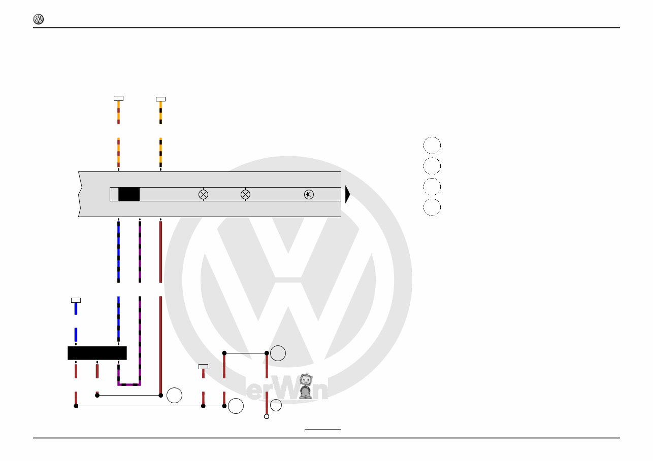
1.2l petrol engine , CGPA,CGPB
From May 2009
Polo
Current Flow Diagram
No. 1 / 1
11.2009
P
rote
cte
d
b
y
c
o
p
yrig
ht.
C
o
p
yin
g
fo
r
p
riv
a
t
e
o
r
c
o
m
m
e
r
c
i
a
l
p
u
r
p
o
s
e
s
,
i
n
p
a
r
t
o
r
i
n
wh
o
l
e
,
i
s
n
o
t
p
e
r
m
itte
d
u
n
le
s
s
a
uth
o
ris
e
d
b
y
V
olk
s
w
a
g
e
n
A
G
.
V
olks
w
a
g
e
n
A
G
d
o
e
s
n
ot
g
u
ara
nte
e
o
r
a
c
c
e
p
t
a
n
y
lia
b
ilit
y
w
it
h
r
e
s
p
e
c
t
t
o
t
h
e
c
o
r
r
e
c
t
n
e
s
s
o
f
i
n
f
o
r
m
a
ti
o
n
in
t
h
is
d
o
c
u
m
e
n
t.
C
o
p
yrig
ht
b
y
V
olk
s
w
a
g
e
n
A
G
.
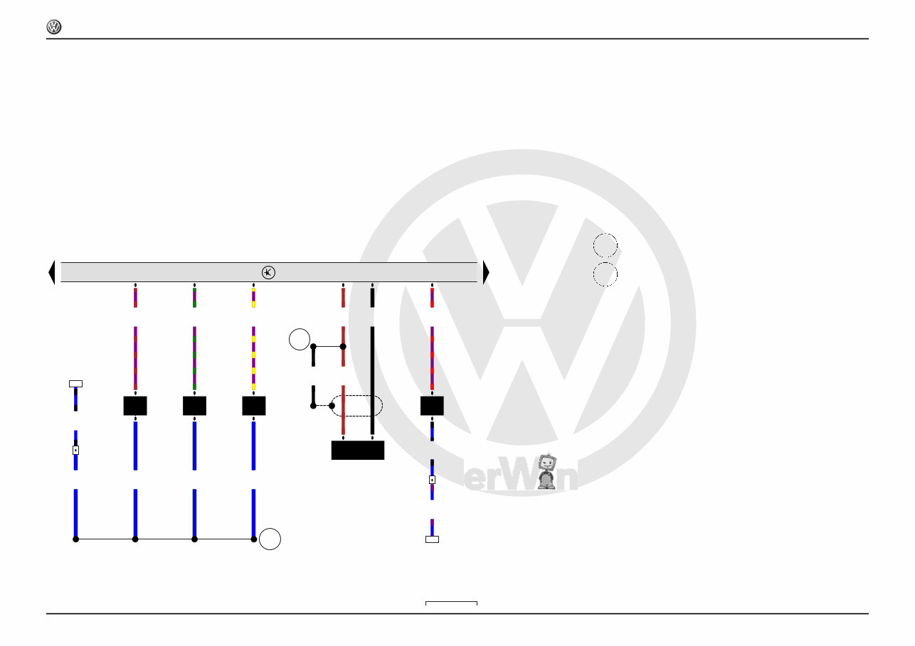
1 2 3 4 5 6 7 8 9 10 11 12 13 14
6R1-00102110
SA
SB
C
G
A
624
B
M
SA1 SA3
SB3
D
30 30
S P 15 50b 75 50
HF S HF S
A15
J682
30 87 86 85
25.0
sw
-
25.0
sw
30
16.0
sw
B+
0.5
sw/bl
37
3b
16.0
rt
16
4.0
sw
15
4.0
sw
T8a
/6
2.5
rt/sw
T8a
/1
2
4.0
rt
24
T8a
/7
2.5
rt
22
T8a
/3
0.5
rt/sw
45
T8a
/5
1.0
sw/rt
20
T8a
/8
0.5
bl
T2
/1
61
T2aa
/1
0.5
br
T2aa
/2
T2
/2
DF
0.5
bl
40
T2aa
/1
0.35
vi/gn
31
T2aa
/2
0.5
sw
131
6
0.5
br
30
4
2.5
rt/sw
2.5
rt/sw
8
13
8
T1m
/1
4.0
sw
25
1.5
sw/rt
27
T8a
/2
1.5
sw
3a
37
16
15 24 22
45 20
40 31
131 30 8
13
25
27
ws = white
sw = black
ro = red
br = brown
gn = green
bl = blue
gr = grey
li = purple
ge = yellow
or = orange
rs = pink
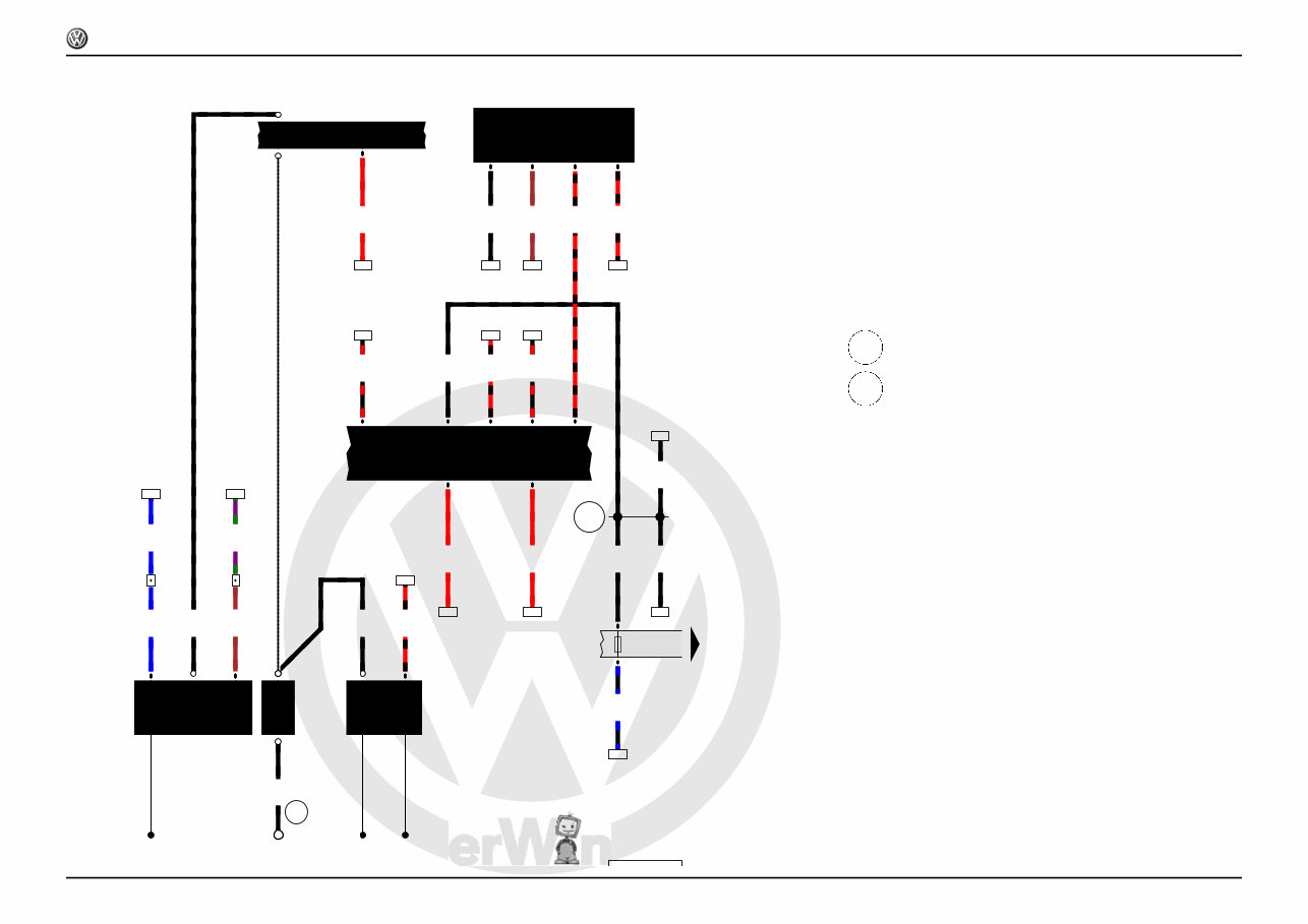
Battery, Starter, Ignition/starter switch, Terminal 50 voltage
supply relay, Fuse holder A, Fuse holder B
A Battery
B Starter
C Alternator
D Ignition/starter switch
J682 Terminal 50 voltage supply relay
SA Fuse holder A
SA1 Fuse 1 in fuse holder A
SB3 Fuse 3 on fuse holder B
SA3 Fuse 3 in fuse holder A
SB Fuse holder B
T1m Single connector
T2 2-pin connector
T2aa 2-pin connector
T8a 8-pin connector
624 Earth point, starter battery
A15 Positive connection (15), in instrument wiring harness
Polo
Current Flow Diagram
No. 1 / 2
11.2009
P
rote
cte
d
b
y
c
o
p
yrig
ht.
C
o
p
yin
g
fo
r
p
riv
a
t
e
o
r
c
o
m
m
e
r
c
i
a
l
p
u
r
p
o
s
e
s
,
i
n
p
a
r
t
o
r
i
n
wh
o
l
e
,
i
s
n
o
t
p
e
r
m
itte
d
u
n
le
s
s
a
uth
o
ris
e
d
b
y
V
olk
s
w
a
g
e
n
A
G
.
V
olks
w
a
g
e
n
A
G
d
o
e
s
n
ot
g
u
ara
nte
e
o
r
a
c
c
e
p
t
a
n
y
lia
b
ilit
y
w
it
h
r
e
s
p
e
c
t
t
o
t
h
e
c
o
r
r
e
c
t
n
e
s
s
o
f
i
n
f
o
r
m
a
ti
o
n
in
t
h
is
d
o
c
u
m
e
n
t.
C
o
p
yrig
ht
b
y
V
olk
s
w
a
g
e
n
A
G
.
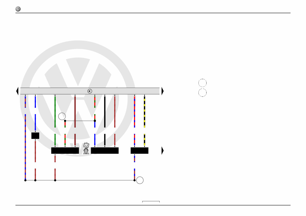
15 16 17 18 19 20 21 22 23 24 25 26 27 28
6R1-00103110
SB SB55 SB31 SB30 SB10 SB28 SB35
J17
85
86 30
87
A151
A52
B170
A40
J643
85
86 30
87
A32
A99
SB32 SB26 SB19
J680
87 86
85 30
A33
SB21 SB23
1.5
sw/vi
55
55b
1.0
bl/sw
57
31b
1.0
bl/vi
69
30b
1.0
sw/bl
98
10b
1.5
bl/rt
105
28b
0.5
sw/ge
30
35b
1.5
sw/vi
32
1.5
sw/vi
55a
0.5
sw/vi
35a
1.5
rt
34
16.0
rt
7
10.0
rt
6.0
rt
6.0
rt
4.0
rt
4.0
rt
20
16
1
2.5
rt
1
0.5
rt
33
3
2.5
ws/rt
2
4.0
ws/rt
28a
4.0
ws/rt
2
0.5
bl/ge
49
5
0.35
bl/ge
32
5
0.5
sw/bl
36
3
1.5
bl/ws
114
32b
1.5
sw/ge
131
26b
4.0
sw
14
9a
4.0
rt
9
2.5
rt
11
1.0
sw/rt
7
19a
0.5
sw/br
41
19b
4.0
rt
1
4.0
sw
14
2
0.5
br
30
4
0.5
sw/rt
3
1.5
sw/rt
11
0.5
sw/rt
42
10.0
rt
20a
1.0
rt/vi
44
21b
1.0
rt/ws
43
23b
55 57 69 98 105 30
32
34
7
20
16 33
49 32
36
114 131
14
9 11
7
41
14 30
11 42
44 43
ws = white
sw = black
ro = red
br = brown
gn = green
bl = blue
gr = grey
li = purple
ge = yellow
or = orange
rs = pink
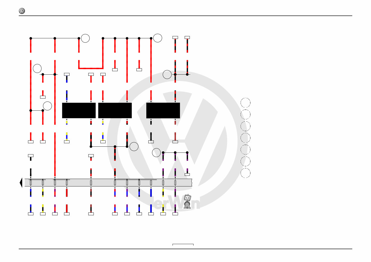
Fuel pump relay, Fuel supply relay, Terminal 75 voltage
supply relay 1, Fuse holder B
J17 Fuel pump relay
J643 Fuel supply relay
J680 Terminal 75 voltage supply relay 1
SB Fuse holder B
SB10 Fuse 10 on fuse holder B
SB19 Fuse 19 on fuse holder B
SB21 Fuse 21 on fuse holder B
SB23 Fuse 23 on fuse holder B
SB26 Fuse 26 on fuse holder B
SB28 Fuse 28 on fuse holder B
SB30 Fuse 30 on fuse holder B
SB31 Fuse 31 on fuse holder B
SB32 Fuse 32 on fuse holder B
SB35 Fuse 35 on fuse holder B
SB55 Fuse 55 on fuse holder B
A32 Positive connection (30), in dash panel wiring harness
A33 Connection (75), in dash panel wiring harness
A40 Positive connection 1 (30), in dash panel wiring harness
A52 Positive connection 2 (30), in dash panel wiring harness
A99 Connection 1 (87) in dash panel wiring harness
A151 Connection 4 (87) in dash panel wiring harness
B170 Positive connection 2 (30), in interior wiring harness
Polo
Current Flow Diagram
No. 1 / 3
11.2009
P
rote
cte
d
b
y
c
o
p
yrig
ht.
C
o
p
yin
g
fo
r
p
riv
a
t
e
o
r
c
o
m
m
e
r
c
i
a
l
p
u
r
p
o
s
e
s
,
i
n
p
a
r
t
o
r
i
n
wh
o
l
e
,
i
s
n
o
t
p
e
r
m
itte
d
u
n
le
s
s
a
uth
o
ris
e
d
b
y
V
olk
s
w
a
g
e
n
A
G
.
V
olks
w
a
g
e
n
A
G
d
o
e
s
n
ot
g
u
ara
nte
e
o
r
a
c
c
e
p
t
a
n
y
lia
b
ilit
y
w
it
h
r
e
s
p
e
c
t
t
o
t
h
e
c
o
r
r
e
c
t
n
e
s
s
o
f
i
n
f
o
r
m
a
ti
o
n
in
t
h
is
d
o
c
u
m
e
n
t.
C
o
p
yrig
ht
b
y
V
olk
s
w
a
g
e
n
A
G
.
29 30 31 32 33 34 35 36 37 38 39 40 41 42
6R1-00104110
J623
281
281
131
640
G79 G185
J519
J271
86 86a
85 30
87
A38 B169
80
2.5
br
T14
/7
2.5
br
T14
/7
2.5
br
T80
/28
2.5
br
T80
/2
6.0
br
0.35
ge/bl
T6b
/1
T80
/18
0.35
br/rt
T6b
/6
T80
/45
0.35
ge/vi
T6b
/5
T80
/19
0.35
bl
T6b
/3
T80
/7
0.35
br/gn
T6b
/4
T80
/33
0.35
gr/ge
T6b
/2
T80
/8
2.5
br
95
0.5
sw/ge
26
T80
/27
0.35
bl/gn
T80
/9
1
1.5
sw/vi
28
8
0.5
sw/bl
0.5
sw/bl
31
35
6
0.35
sw/bl
T80
/4
0.5
sw/bl
13
1.5
rt
2
1.5
rt
15
0.5
rt
21
0.35
bl/ge
18
T80
/26
0.5
sw/bl
18
0.5
br
4
1.5
br
120
0.5
sw/br
20
T73a
/42
0.5
bl
2
T73b
/49
0.35
vi/gn
4
T80
/11
0.5
br
11
0.5
br
27
0.5
sw/rt
28
T73b
/51
95
26
28
31
35
13 15 21
18
18
120
20 2
4
11
27
28
ws = white
sw = black
ro = red
br = brown
gn = green
bl = blue
gr = grey
li = purple
ge = yellow
or = orange
rs = pink
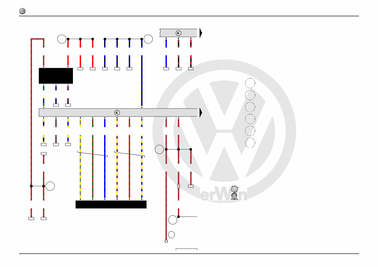
Accelerator position sender, Accelerator position sender 2,
Main relay, Onboard supply control unit, Engine control unit
G79 Accelerator position sender
G185 Accelerator position sender 2
J271 Main relay
J519 Onboard supply control unit
J623 Engine control unit
T6b 6-pin connector
T14 14-pin connector
T73a 73-pin connector
T73b 73-pin connector
T80 80-pin connector
80 Earth connection 1, in dash panel wiring harness
131 Earth connection 2, in engine compartment wiring harness
281 Earth point 1, engine prewiring harness
640 Earth point 2, left in engine compartment
A38 Positive connection 2 (15a) in dash panel wiring harness
B169 Positive connection 1 (30), in interior wiring harness
Polo
Current Flow Diagram
No. 1 / 4
11.2009
P
rote
cte
d
b
y
c
o
p
yrig
ht.
C
o
p
yin
g
fo
r
p
riv
a
t
e
o
r
c
o
m
m
e
r
c
i
a
l
p
u
r
p
o
s
e
s
,
i
n
p
a
r
t
o
r
i
n
wh
o
l
e
,
i
s
n
o
t
p
e
r
m
itte
d
u
n
le
s
s
a
uth
o
ris
e
d
b
y
V
olk
s
w
a
g
e
n
A
G
.
V
olks
w
a
g
e
n
A
G
d
o
e
s
n
ot
g
u
ara
nte
e
o
r
a
c
c
e
p
t
a
n
y
lia
b
ilit
y
w
it
h
r
e
s
p
e
c
t
t
o
t
h
e
c
o
r
r
e
c
t
n
e
s
s
o
f
i
n
f
o
r
m
a
ti
o
n
in
t
h
is
d
o
c
u
m
e
n
t.
C
o
p
yrig
ht
b
y
V
olk
s
w
a
g
e
n
A
G
.
43 44 45 46 47 48 49 50 51 52 53 54 55 56
6R1-00105110
J623
N70 N127 N291
Q Q Q
P P P
F2
91
15
281
J519
A130
E45
A76
*
B111
0.35
gn/ge
T4b
/4
T80
/71
0.35
gn/br
T4a
/4
T80
/57
0.35
vi/sw
T4c
/4
T80
/76
1.5
sw/vi
T14
/8
1.5
sw/vi
T4c
/3
1.5
sw/vi
T4b
/3
1.5
sw/vi
T4a
/3
1.5
sw/vi
27
T14
/8
1.5
br/ge
T4c
/2
1.5
br/ge
T4b
/2
1.5
br/ge
T4a
/2
2.5
br/ge
1.5
br
T4c
/1
1.5
br
T4b
/1
1.5
br
T4a
/1
0.35
sw/gn
93
T73b
/42
0.35
sw/rt
97
T73a
/43
0.5
bl/ge
21
T73a
/52
0.5
br
133
0.5
rt/sw
10
T73b
/50
0.35
or/br
107
T73b
/18
0.35
or/sw
102
T73b
/19
0.35
ws
T80
/24
GRA
0.35
ws
T73b
/45
0.35
ws
T41
/26
0.35
ws
T41
/29
0.5
gr/ws
T73b
/37
0.35
gr/ws
T80
/29
k-diag
0.5
gr/ws
T16b
/7
1.0
rt/vi
17
T73a
/66
0.5
rt/ws
T73b
/39
1.0
rt/ws
18
27
93 97 21
133
10 107 102 17
18
ws = white
sw = black
ro = red
br = brown
gn = green
bl = blue
gr = grey
li = purple
ge = yellow
or = orange
rs = pink
Cruise control system switch, Onboard supply control unit,
Engine control unit, Ignition coil 1 with output stage, Ignition
coil 2 with output stage, Ignition coil 3 with output stage
E45 Cruise control system switch
J519 Onboard supply control unit
J623 Engine control unit
N70 Ignition coil 1 with output stage
N127 Ignition coil 2 with output stage
N291 Ignition coil 3 with output stage
P Spark plug connector
Q Spark plugs
T4a 4-pin connector
T4b 4-pin connector
T4c 4-pin connector
T14 14-pin connector
T16b 16-pin connector
T41 41-pin connector
T73a 73-pin connector
T73b 73-pin connector
T80 80-pin connector
15 Earth point, on cylinder head
91
Earth connection 1, in fully electronic ignition system wiring
harness
281 Earth point 1, engine prewiring harness
A76 Connection (K-diagnosis wire), in dash panel wiring harness
A130 Connection (CCS), in dash panel wiring harness
B111 Positive connection 1 (30a), in interior wiring harness
F2
Positive connection (87a), in fully electronic ignition wiring
harness
* Diagnostic connection
Polo
Current Flow Diagram
No. 1 / 5
11.2009
P
rote
cte
d
b
y
c
o
p
yrig
ht.
C
o
p
yin
g
fo
r
p
riv
a
t
e
o
r
c
o
m
m
e
r
c
i
a
l
p
u
r
p
o
s
e
s
,
i
n
p
a
r
t
o
r
i
n
wh
o
l
e
,
i
s
n
o
t
p
e
r
m
itte
d
u
n
le
s
s
a
uth
o
ris
e
d
b
y
V
olk
s
w
a
g
e
n
A
G
.
V
olks
w
a
g
e
n
A
G
d
o
e
s
n
ot
g
u
ara
nte
e
o
r
a
c
c
e
p
t
a
n
y
lia
b
ilit
y
w
it
h
r
e
s
p
e
c
t
t
o
t
h
e
c
o
r
r
e
c
t
n
e
s
s
o
f
i
n
f
o
r
m
a
ti
o
n
in
t
h
is
d
o
c
u
m
e
n
t.
C
o
p
yrig
ht
b
y
V
olk
s
w
a
g
e
n
A
G
.
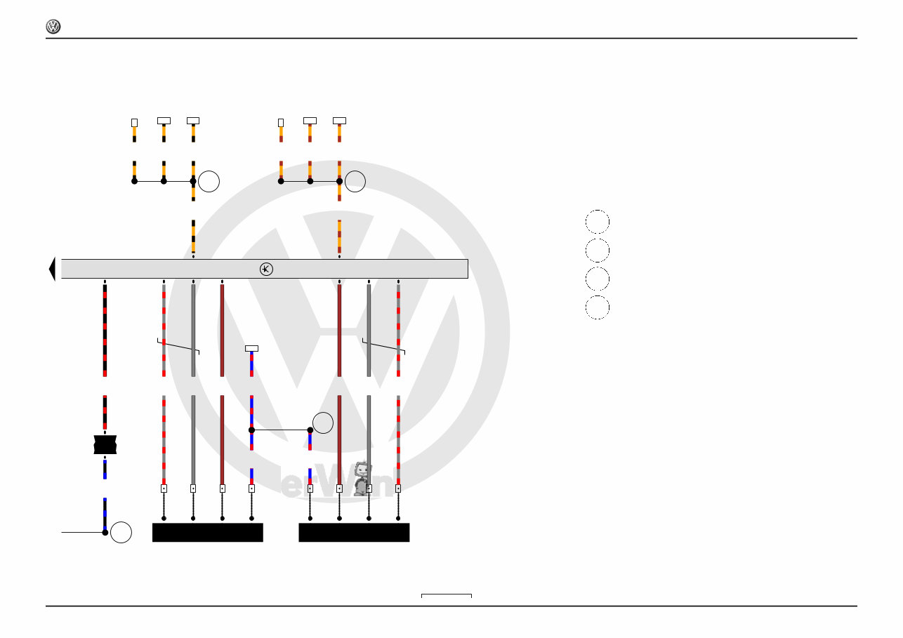
57 58 59 60 61 62 63 64 65 66 67 68 69 70
6R1-00106110
J623
N30 N31 N32
D140
G61
200
N80
0.35
vi/br
T2c
/2
T80
/79
0.35
vi/gn
T2d
/2
T80
/73
0.35
vi/ge
T2e
/2
T80
/65
0.5
bl/ws
T2e
/1
0.5
bl/ws
T2d
/1
0.5
bl/ws
T2c
/1
1.0
bl/ws
T14
/5
1.0
bl/sw
24
T14
/5
0.35
ws
T2g
/1
T80
/77
0.35
sw
0.35
br
T2g
/2
0.5
br
T80
/63
1.0
vi/rt
T2i
/2
T80
/59
1.0
bl/sw
T2i
/1
T14
/6
1.0
bl/vi
23
T14
/6
24
23
ws = white
sw = black
ro = red
br = brown
gn = green
bl = blue
gr = grey
li = purple
ge = yellow
or = orange
rs = pink
Knock sensor 1, Engine control unit, Injector, cylinder 1,
Injector, cylinder 2, Injector, cylinder 3, Activated charcoal
filter solenoid valve 1
G61 Knock sensor 1
J623 Engine control unit
N30 Injector, cylinder 1
N31 Injector, cylinder 2
N32 Injector, cylinder 3
N80 Activated charcoal filter solenoid valve 1
T2c 2-pin connector
T2d 2-pin connector
T2e 2-pin connector
T2g 2-pin connector
T2i 2-pin connector
T14 14-pin connector
T80 80-pin connector
200
Earth connection (screening), in engine compartment wiring
harness
D140 Connection (injectors), in engine prewiring harness
Polo
Current Flow Diagram
No. 1 / 6
11.2009
P
rote
cte
d
b
y
c
o
p
yrig
ht.
C
o
p
yin
g
fo
r
p
riv
a
t
e
o
r
c
o
m
m
e
r
c
i
a
l
p
u
r
p
o
s
e
s
,
i
n
p
a
r
t
o
r
i
n
wh
o
l
e
,
i
s
n
o
t
p
e
r
m
itte
d
u
n
le
s
s
a
uth
o
ris
e
d
b
y
V
olk
s
w
a
g
e
n
A
G
.
V
olks
w
a
g
e
n
A
G
d
o
e
s
n
ot
g
u
ara
nte
e
o
r
a
c
c
e
p
t
a
n
y
lia
b
ilit
y
w
it
h
r
e
s
p
e
c
t
t
o
t
h
e
c
o
r
r
e
c
t
n
e
s
s
o
f
i
n
f
o
r
m
a
ti
o
n
in
t
h
is
d
o
c
u
m
e
n
t.
C
o
p
yrig
ht
b
y
V
olk
s
w
a
g
e
n
A
G
.
71 72 73 74 75 76 77 78 79 80 81 82 83 84
6R1-00107110
J623
G40
283
G28
D141
G71
P
J
G62
J
G42
G186
0.35
ws/ge
T3c
/2
T80
/60
0.5
rt/bl
T3c
/1
T80
/64
0.5
br/bl
T3c
/3
0.5
br
T3d
/3
T80
/67
0.5
ws
T3d
/2
T80
/53
0.5
bl
T3d
/1
0.35
rt/gn
T80
/62
0.5
rt/gn
T4d
/3
0.35
br/ws
T4d
/4
T80
/70
0.35
gn
T4d
/2
T80
/56
0.35
br
T4d
/1
0.35
br
T2h
/2
0.35
bl
T2h
/1
T80
/74
0.35
br/bl
T80
/54
ws = white
sw = black
ro = red
br = brown
gn = green
bl = blue
gr = grey
li = purple
ge = yellow
or = orange
rs = pink
Engine speed sender, Hall sender, Intake air temperature
sender, Coolant temperature sender, Intake manifold
pressure sender, Throttle valve drive for electric throttle,
Engine control unit
G28 Engine speed sender
G40 Hall sender
G42 Intake air temperature sender
G62 Coolant temperature sender
G71 Intake manifold pressure sender
G186 Throttle valve drive for electric throttle
J623 Engine control unit
T2h 2-pin connector
T3c 3-pin connector
T3d 3-pin connector
T4d 4-pin connector
T80 80-pin connector
283 Earth point 2, engine prewiring harness
D141 Connection (5V) in engine prewiring harness
Polo
Current Flow Diagram
No. 1 / 7
11.2009
P
rote
cte
d
b
y
c
o
p
yrig
ht.
C
o
p
yin
g
fo
r
p
riv
a
t
e
o
r
c
o
m
m
e
r
c
i
a
l
p
u
r
p
o
s
e
s
,
i
n
p
a
r
t
o
r
i
n
wh
o
l
e
,
i
s
n
o
t
p
e
r
m
itte
d
u
n
le
s
s
a
uth
o
ris
e
d
b
y
V
olk
s
w
a
g
e
n
A
G
.
V
olks
w
a
g
e
n
A
G
d
o
e
s
n
ot
g
u
ara
nte
e
o
r
a
c
c
e
p
t
a
n
y
lia
b
ilit
y
w
it
h
r
e
s
p
e
c
t
t
o
t
h
e
c
o
r
r
e
c
t
n
e
s
s
o
f
i
n
f
o
r
m
a
ti
o
n
in
t
h
is
d
o
c
u
m
e
n
t.
C
o
p
yrig
ht
b
y
V
olk
s
w
a
g
e
n
A
G
. 85 86 87 88 89 90 91 92 93 94 95 96 97 98
6R1-00108110
J623
J338
M
G186 G188 G187
F
HL HL
2 1
D101
J104
D73
132
B27
0.5
bl/ws
T6a
/5
T80
/66
-
0.5
br/bl
T6a
/3
T80
/80
0.35
br/rt
T80
/61
T6a
/6
0.35
vi
T6a
/1
T80
/68
0.35
vi/rt
T6a
/2
T80
/55
0.35
rt/ge
T6a
/4
T80
/75
0.35
sw/gn
T80
/51
0.5
sw/gn
T4e
/1
0.35
sw/gn
50
0.5
sw/gn
*
T38
/8
1.0
sw/rt
1.0
sw/rt
97
92
T38
/30
0.35
sw/rt
T80
/23
0.5
sw/rt
T4e
/3
0.35
sw/rt
51
0.5
br
T4e
/2
2.5
br
42
0.5
sw/bl
T4e
/4
1.0
sw/bl
15
50
97
92
51 42
15
ws = white
sw = black
ro = red
br = brown
gn = green
bl = blue
gr = grey
li = purple
ge = yellow
or = orange
rs = pink
Brake light switch, Throttle valve drive for electric throttle,
Throttle valve drive angle sender 1 for electric throttle,
Throttle valve drive angle sender 2 for electric throttle, ABS
control unit, Throttle valve module, Engine control unit
F Brake light switch
G186 Throttle valve drive for electric throttle
G187 Throttle valve drive angle sender 1 for electric throttle
G188 Throttle valve drive angle sender 2 for electric throttle
J104 ABS control unit
J338 Throttle valve module
J623 Engine control unit
T4e 4-pin connector
T6a 6-pin connector
T38 38-pin connector
T80 80-pin connector
132 Earth connection 3, in engine compartment wiring harness
B277 Positive connection 1 (15a) in main wiring harness
D73 Positive connection (54), in engine compartment wiring harness
D101 Connection 1 in engine compartment wiring harness
* Only models with electronic standardisation program (ESP)
Polo
Current Flow Diagram
No. 1 / 8
11.2009
P
rote
cte
d
b
y
c
o
p
yrig
ht.
C
o
p
yin
g
fo
r
p
riv
a
t
e
o
r
c
o
m
m
e
r
c
i
a
l
p
u
r
p
o
s
e
s
,
i
n
p
a
r
t
o
r
i
n
wh
o
l
e
,
i
s
n
o
t
p
e
r
m
itte
d
u
n
le
s
s
a
uth
o
ris
e
d
b
y
V
olk
s
w
a
g
e
n
A
G
.
V
olks
w
a
g
e
n
A
G
d
o
e
s
n
ot
g
u
ara
nte
e
o
r
a
c
c
e
p
t
a
n
y
lia
b
ilit
y
w
it
h
r
e
s
p
e
c
t
t
o
t
h
e
c
o
r
r
e
c
t
n
e
s
s
o
f
i
n
f
o
r
m
a
ti
o
n
in
t
h
is
d
o
c
u
m
e
n
t.
C
o
p
yrig
ht
b
y
V
olk
s
w
a
g
e
n
A
G
.
99 100 101 102 103 104 105 106 107 108 109 110 111 112
6R1-00109110
J623
B277
B277
G476
G39
l
Z19 G130
l
Z29
E29
B390
*
B383
*
0.5
sw/bl
T4f
/2
0.35
ws/rt
T4f
/3
T80
/38
T4g
/1
T4g
/2
T4g
/3
T4g
/4
0.35
gr/rt
T4g
/4
T80
/46
0.35
gr/ws
T4g
/3
T80
/20
1.0
br/ws
T4g
/2
T80
/1
T4h
/1
T4h
/2
T4h
/3
T4h
/4
0.35
gr/rt
T4h
/4
T80
/47
0.35
gr/ws
T4h
/3
T80
/21
1.0
br/ws
T4h
/2
T80
/13
1.0
bl/rt
T4g
/1
1.5
bl/rt
T4h
/1
1.5
bl/rt
22
0.35
or/br
T80
/32
a-can-l
0.35
or/br
116
0.35
or/br
47
0.35
or/br
T16b
/11
0.35
or/sw
T80
/31
a-can-h
0.35
or/sw
118
0.35
or/sw
46
0.35
or/sw
T16b
/3
22
116 47 118 46
ws = white
sw = black
ro = red
br = brown
gn = green
bl = blue
gr = grey
li = purple
ge = yellow
or = orange
rs = pink
Lambda probe, Lambda probe after catalytic converter,
Clutch position sender, Engine control unit, Lambda probe
heater, Lambda probe 1 heater after catalytic converter
G39 Lambda probe
G130 Lambda probe after catalytic converter
G476 Clutch position sender
J623 Engine control unit
T4f 4-pin connector
T4g 4-pin connector
T4h 4-pin connector
T16b 16-pin connector
T80 80-pin connector
Z19 Lambda probe heater
Z29 Lambda probe 1 heater after catalytic converter
B277 Positive connection 1 (15a) in main wiring harness
B383 Connection 1 (powertrain CAN bus, high), in main wiring harness
B390 Connection 1 (powertrain CAN bus, low), in main wiring harness
E29 Connection, in engine wiring harness
* Diagnostic connection
Polo
Current Flow Diagram
No. 1 / 9
11.2009
P
rote
cte
d
b
y
c
o
p
yrig
ht.
C
o
p
yin
g
fo
r
p
riv
a
t
e
o
r
c
o
m
m
e
r
c
i
a
l
p
u
r
p
o
s
e
s
,
i
n
p
a
r
t
o
r
i
n
wh
o
l
e
,
i
s
n
o
t
p
e
r
m
itte
d
u
n
le
s
s
a
uth
o
ris
e
d
b
y
V
olk
s
w
a
g
e
n
A
G
.
V
olks
w
a
g
e
n
A
G
d
o
e
s
n
ot
g
u
ara
nte
e
o
r
a
c
c
e
p
t
a
n
y
lia
b
ilit
y
w
it
h
r
e
s
p
e
c
t
t
o
t
h
e
c
o
r
r
e
c
t
n
e
s
s
o
f
i
n
f
o
r
m
a
ti
o
n
in
t
h
is
d
o
c
u
m
e
n
t.
C
o
p
yrig
ht
b
y
V
olk
s
w
a
g
e
n
A
G
.
113 114 115 116 117 118 119 120 121 122 123 124 125 126
6R1-00110110
G6
M
G
81
K
269
199
606
J285
G1 K2 K105
1.5
bl/ws
25
T5
/1
1.5
br
T5
/5
0.35
vi/sw
T32
/1
T5
/3
0.35
br/ws
T5
/2
0.35
br/ws
T32
/20
0.35
bl/sw
T5
/4
T32
/2
1.5
br
29
2.5
br
6.0
br
0.35
or/br
108
T32
/29
a-can-l
0.35
or/sw
103
T32
/28
a-can-h
25
29
108 103
ws = white
sw = black
ro = red
br = brown
gn = green
bl = blue
gr = grey
li = purple
ge = yellow
or = orange
rs = pink
Fuel gauge sender, Fuel gauge, Fuel system pressurisation
pump, Control unit in dash panel insert, Dash panel insert,
Alternator warning lamp, Reserve fuel warning lamp
G Fuel gauge sender
G1 Fuel gauge
G6 Fuel system pressurisation pump
J285 Control unit in dash panel insert
K Dash panel insert
K2 Alternator warning lamp
K105 Reserve fuel warning lamp
T5 5-pin connector
T32 32-pin connector
81 Earth connection 1, in dash panel wiring harness
199 Earth connection 3, in dash panel wiring harness
269 Earth connection (sender earth) 1, in dash panel wiring harness
606 Earth point, under the centre console near gear stick
Polo
Current Flow Diagram
No. 1 / 10
11.2009
You're Reading a Preview
What's Included?
Fast Download Speeds
Online & Offline Access
Access PDF Contents & Bookmarks
Full Search Facility
Print one or all pages of your manual
$52.99
Viewed 58 Times Today


Secure transaction
What's Included?
Fast Download Speeds
Online & Offline Access
Access PDF Contents & Bookmarks
Full Search Facility
Print one or all pages of your manual
$52.99
The 2016 Volkswagen Polo GTI Download Service & Repair Manual is a comprehensive guide designed to assist owners in maintaining and repairing their vehicles with ease.
Featuring detailed instructions and diagrams, this manual covers various models of the 2016 Volkswagen Polo GTI, including:
- 2016 Volkswagen Polo GTI 1.8L MPFI Turbo DOHC
- 2016 Volkswagen Polo GTI 1.8L TSI Petrol
- 2016 Volkswagen Polo GTI 1.8L TSI Petrol DSG
Whether you are a seasoned mechanic or a Volkswagen enthusiast, this service and repair manual serves as a valuable resource for maintaining optimal performance and extending the lifespan of your Polo GTI.
If you are looking to take the DIY approach to repair and servicing, then the 2016 Volkswagen Polo GTI Download Service & Repair Manual is the perfect companion. Order yours today and ensure your Polo GTI continues to run smoothly for years to come.


