

2010 SKODA Superb Combi Download Service & Repair Manual
What's Included?
Fast Download Speeds
Offline Viewing
Access Contents & Bookmarks
Full Search Facility
Print one or all pages of your manual
Protected by copyright. Copying for private or commercial purposes, in part or in whole, is not permitted
unless authorised by ŠKODA AUTO A. S. ŠKODA AUTO A. S. does not guarantee or accept any liability
with respect to the correctness of information in this document. Copyright by ŠKODA AUTO A. S.�
Workshop Manual
Superb II 2008 ➤
Superb II 2011 ➤
3.6/191 kW FSI Engine
Engine ID
CDV
A
Edition 03.2016
Service
Service Department. Technical Information

Protected by copyright. Copying for private or commercial purposes, in part or in whole, is not permitted
unless authorised by ŠKODA AUTO A. S. ŠKODA AUTO A. S. does not guarantee or accept any liability
with respect to the correctness of information in this document. Copyright by ŠKODA AUTO A. S.�
List of Workshop Manual Repair Groups
Repair Group
00 - Technical data
01 - Self-diagnosis
10 - Removing and installing engine
13 - Crankshaft group
15 - Cylinder head, valve gear
17 - Lubrication
19 - Cooling
20 - Fuel supply system
24 - Mixture preparation - injection
26 - Exhaust system
28 - Ignition system
Technical information should always be available to the foremen and mechanics, because their
careful and constant adherence to the instructions is essential to ensure vehicle road-worthiness and
safety. In addition, the normal basic safety precautions for working on motor vehicles must, as a
matter of course, be observed.
Service
All rights reserved.
No reproduction without prior agreement from publisher.
Copyright © 2016 ŠKODA AUTO a. s. D3E8019DF87

Protected by copyright. Copying for private or commercial purposes, in part or in whole, is not permitted
unless authorised by ŠKODA AUTO A. S. ŠKODA AUTO A. S. does not guarantee or accept any liability
with respect to the correctness of information in this document. Copyright by ŠKODA AUTO A. S.�
Contents
00 - Technical data . . . . . . . . . . . . . . . . . . . . . . . . . . . . . . . . . . . . . . . . . . . . . . . . . . . . 1
1 Technical data . . . . . . . . . . . . . . . . . . . . . . . . . . . . . . . . . . . . . . . . . . . . . . . . . . . . . . . . . . 1
1.1 Engine number . . . . . . . . . . . . . . . . . . . . . . . . . . . . . . . . . . . . . . . . . . . . . . . . . . . . . . . . . . 1
1.2 Engine characteristics . . . . . . . . . . . . . . . . . . . . . . . . . . . . . . . . . . . . . . . . . . . . . . . . . . . . 1
01 - Self-diagnosis . . . . . . . . . . . . . . . . . . . . . . . . . . . . . . . . . . . . . . . . . . . . . . . . . . . . 3
1 Self diagnosis, safety measures, cleanliness regulations, directions . . . . . . . . . . . . . . . . . . 3
1.1 Self-diagnosis . . . . . . . . . . . . . . . . . . . . . . . . . . . . . . . . . . . . . . . . . . . . . . . . . . . . . . . . . . . . 3
1.2 Safety precautions when working on fuel supply system . . . . . . . . . . . . . . . . . . . . . . . . . . 3
1.3 Reduce pressure in the high-pressure system . . . . . . . . . . . . . . . . . . . . . . . . . . . . . . . . . . 4
1.4 Rules of cleanliness to observe when working on the fuel supply system . . . . . . . . . . . . . . 5
1.5 Safety measures to apply when working on the fuel injection and ignition system . . . . . . 5
1.6 General notes on the injection system . . . . . . . . . . . . . . . . . . . . . . . . . . . . . . . . . . . . . . . . 6
1.7 General notes on the ignition system . . . . . . . . . . . . . . . . . . . . . . . . . . . . . . . . . . . . . . . . . . 6
1.8 Additional instructions when undertaking assembly work on the air-conditioning system . . 7
10 - Removing and installing engine . . . . . . . . . . . . . . . . . . . . . . . . . . . . . . . . . . . . . . 8
1 Removing and installing engine . . . . . . . . . . . . . . . . . . . . . . . . . . . . . . . . . . . . . . . . . . . . . . 8
1.1 Removing engine . . . . . . . . . . . . . . . . . . . . . . . . . . . . . . . . . . . . . . . . . . . . . . . . . . . . . . . . 8
1.2 Securing the engine to the assembly stand . . . . . . . . . . . . . . . . . . . . . . . . . . . . . . . . . . . . 14
1.3 Installing the engine . . . . . . . . . . . . . . . . . . . . . . . . . . . . . . . . . . . . . . . . . . . . . . . . . . . . . . 15
2 Assembly bracket . . . . . . . . . . . . . . . . . . . . . . . . . . . . . . . . . . . . . . . . . . . . . . . . . . . . . . . . 19
2.1 Tightening torques of the unit mounting . . . . . . . . . . . . . . . . . . . . . . . . . . . . . . . . . . . . . . . . 19
2.2 Checking and adjusting the assembly bracket . . . . . . . . . . . . . . . . . . . . . . . . . . . . . . . . . . 20
13 - Crankshaft group . . . . . . . . . . . . . . . . . . . . . . . . . . . . . . . . . . . . . . . . . . . . . . . . . . 23
1 V-ribbed belt drive . . . . . . . . . . . . . . . . . . . . . . . . . . . . . . . . . . . . . . . . . . . . . . . . . . . . . . . . 23
1.1 V-ribbed belt - Summary of components . . . . . . . . . . . . . . . . . . . . . . . . . . . . . . . . . . . . . . 23
1.2 Removing and installing V-ribbed belt . . . . . . . . . . . . . . . . . . . . . . . . . . . . . . . . . . . . . . . . 24
2 Disassembling and assembling engine . . . . . . . . . . . . . . . . . . . . . . . . . . . . . . . . . . . . . . . . 26
2.1 Chain drive - Summary of components . . . . . . . . . . . . . . . . . . . . . . . . . . . . . . . . . . . . . . . . 26
2.2 Crankshaft drive - Summary of components . . . . . . . . . . . . . . . . . . . . . . . . . . . . . . . . . . . . 29
2.3 Removing and installing bracket for auxiliary units . . . . . . . . . . . . . . . . . . . . . . . . . . . . . . 31
3 Sealing flanges and flywheel . . . . . . . . . . . . . . . . . . . . . . . . . . . . . . . . . . . . . . . . . . . . . . . . 32
3.1 Sealing flanges and flywheel - Summary of components . . . . . . . . . . . . . . . . . . . . . . . . . . 32
3.2 Covers for timing chains - Summary of components . . . . . . . . . . . . . . . . . . . . . . . . . . . . . . 33
3.3 Removing and installing gasket ring for crankshaft on gearbox side . . . . . . . . . . . . . . . . . . 34
3.4 Removing and installing the sealing flange on the gearbox side . . . . . . . . . . . . . . . . . . . . 34
3.5 Removing and installing the two-mass flywheel . . . . . . . . . . . . . . . . . . . . . . . . . . . . . . . . . . 37
3.6 Replacing sealing flange on the belt pulley side . . . . . . . . . . . . . . . . . . . . . . . . . . . . . . . . 38
4 Crankshaft . . . . . . . . . . . . . . . . . . . . . . . . . . . . . . . . . . . . . . . . . . . . . . . . . . . . . . . . . . . . . . 41
4.1 Summary of components . . . . . . . . . . . . . . . . . . . . . . . . . . . . . . . . . . . . . . . . . . . . . . . . . . 41
4.2 Install sensor rotor on crankshaft . . . . . . . . . . . . . . . . . . . . . . . . . . . . . . . . . . . . . . . . . . . . 42
4.3 Pulling the needle bearing out of the crankshaft and driving it in . . . . . . . . . . . . . . . . . . . . 43
4.4 Assignment of crankshaft bearing shells (classification) . . . . . . . . . . . . . . . . . . . . . . . . . . 44
5 Pistons and conrods . . . . . . . . . . . . . . . . . . . . . . . . . . . . . . . . . . . . . . . . . . . . . . . . . . . . . . 46
5.1 Assembly overview - piston and conrod . . . . . . . . . . . . . . . . . . . . . . . . . . . . . . . . . . . . . . . . 46
5.2 Inspect piston, piston rings and cylinder bore . . . . . . . . . . . . . . . . . . . . . . . . . . . . . . . . . . 47
5.3 Separating new conrod . . . . . . . . . . . . . . . . . . . . . . . . . . . . . . . . . . . . . . . . . . . . . . . . . . . . 50
15 - Cylinder head, valve gear . . . . . . . . . . . . . . . . . . . . . . . . . . . . . . . . . . . . . . . . . . 52
1 Cylinder head - part 1 . . . . . . . . . . . . . . . . . . . . . . . . . . . . . . . . . . . . . . . . . . . . . . . . . . . . . . 52
Superb II 2008 ➤ , Superb II 2011 ➤
3.6/191 kW FSI Engine - Edition 03.2016
Contents i

Protected by copyright. Copying for private or commercial purposes, in part or in whole, is not permitted
unless authorised by ŠKODA AUTO A. S. ŠKODA AUTO A. S. does not guarantee or accept any liability
with respect to the correctness of information in this document. Copyright by ŠKODA AUTO A. S.�
1.1 Summary of components - cylinder head . . . . . . . . . . . . . . . . . . . . . . . . . . . . . . . . . . . . . . 52
1.2 Removing and installing cylinder head cover . . . . . . . . . . . . . . . . . . . . . . . . . . . . . . . . . . . . 54
1.3 Removing and installing the cylinder head . . . . . . . . . . . . . . . . . . . . . . . . . . . . . . . . . . . . . . 55
1.4 Test timing . . . . . . . . . . . . . . . . . . . . . . . . . . . . . . . . . . . . . . . . . . . . . . . . . . . . . . . . . . . . . . 62
2 Cylinder head - part 2 . . . . . . . . . . . . . . . . . . . . . . . . . . . . . . . . . . . . . . . . . . . . . . . . . . . . . . 68
2.1 Removing and installing camshaft adjuster with timing chain for camshaft drive . . . . . . . . 68
2.2 Install timing chain for oil pump drive and camshaft drive . . . . . . . . . . . . . . . . . . . . . . . . . . 74
2.3 Mechanical vacuum pump - Summary of components . . . . . . . . . . . . . . . . . . . . . . . . . . . . 78
2.4 Removing and installing mechanical vacuum pump . . . . . . . . . . . . . . . . . . . . . . . . . . . . . . 79
2.5 Removing and installing the gasket rings in the cover part . . . . . . . . . . . . . . . . . . . . . . . . 80
2.6 Testing the compression . . . . . . . . . . . . . . . . . . . . . . . . . . . . . . . . . . . . . . . . . . . . . . . . . . 80
2.7 Testing the combustion chamber for tightness . . . . . . . . . . . . . . . . . . . . . . . . . . . . . . . . . . 81
3 Repairing Valve Gear . . . . . . . . . . . . . . . . . . . . . . . . . . . . . . . . . . . . . . . . . . . . . . . . . . . . . . 83
3.1 Assembly overview - valve gear . . . . . . . . . . . . . . . . . . . . . . . . . . . . . . . . . . . . . . . . . . . . . . 83
3.2 Timing case - Summary of components . . . . . . . . . . . . . . . . . . . . . . . . . . . . . . . . . . . . . . . . 85
3.3 Checking the axial play of the camshaft . . . . . . . . . . . . . . . . . . . . . . . . . . . . . . . . . . . . . . . . 86
3.4 Removing and installing camshaft adjustment valves . . . . . . . . . . . . . . . . . . . . . . . . . . . . 86
3.5 Removing and installing camshafts . . . . . . . . . . . . . . . . . . . . . . . . . . . . . . . . . . . . . . . . . . 90
3.6 Camshaft identification . . . . . . . . . . . . . . . . . . . . . . . . . . . . . . . . . . . . . . . . . . . . . . . . . . . . 96
3.7 Replacing valve stem seals . . . . . . . . . . . . . . . . . . . . . . . . . . . . . . . . . . . . . . . . . . . . . . . . 96
3.8 Valve dimensions . . . . . . . . . . . . . . . . . . . . . . . . . . . . . . . . . . . . . . . . . . . . . . . . . . . . . . . . 98
3.9 Inspect valve guides . . . . . . . . . . . . . . . . . . . . . . . . . . . . . . . . . . . . . . . . . . . . . . . . . . . . . . 98
3.10 Reworking valve seats . . . . . . . . . . . . . . . . . . . . . . . . . . . . . . . . . . . . . . . . . . . . . . . . . . . . 98
17 - Lubrication . . . . . . . . . . . . . . . . . . . . . . . . . . . . . . . . . . . . . . . . . . . . . . . . . . . . . . 102
1 Lubrication system . . . . . . . . . . . . . . . . . . . . . . . . . . . . . . . . . . . . . . . . . . . . . . . . . . . . . . . . 102
1.1 Oil pan, oil pump and oil filter holder - Summary of components . . . . . . . . . . . . . . . . . . . . 102
1.2 Removing and installing oil pan . . . . . . . . . . . . . . . . . . . . . . . . . . . . . . . . . . . . . . . . . . . . . . 105
1.3 Removing and installing oil pump . . . . . . . . . . . . . . . . . . . . . . . . . . . . . . . . . . . . . . . . . . . . 107
1.4 Oil filter housing - Summary of components . . . . . . . . . . . . . . . . . . . . . . . . . . . . . . . . . . . . 110
1.5 Testing oil pressure and oil pressure switch . . . . . . . . . . . . . . . . . . . . . . . . . . . . . . . . . . . . 112
19 - Cooling . . . . . . . . . . . . . . . . . . . . . . . . . . . . . . . . . . . . . . . . . . . . . . . . . . . . . . . . . . 115
1 Cooling system . . . . . . . . . . . . . . . . . . . . . . . . . . . . . . . . . . . . . . . . . . . . . . . . . . . . . . . . . . 115
1.1 Parts of cooling system engine side - Summary of components . . . . . . . . . . . . . . . . . . . . 115
1.2 Connection diagram for coolant hoses . . . . . . . . . . . . . . . . . . . . . . . . . . . . . . . . . . . . . . . . 118
1.3 Draining and filling up coolant . . . . . . . . . . . . . . . . . . . . . . . . . . . . . . . . . . . . . . . . . . . . . . 119
2 Coolant pump, coolant regulator . . . . . . . . . . . . . . . . . . . . . . . . . . . . . . . . . . . . . . . . . . . . 122
2.1 Removing and installing coolant pump . . . . . . . . . . . . . . . . . . . . . . . . . . . . . . . . . . . . . . . . 122
2.2 Removing and installing coolant regulator . . . . . . . . . . . . . . . . . . . . . . . . . . . . . . . . . . . . . . 123
2.3 Checking the coolant system for leaktightness . . . . . . . . . . . . . . . . . . . . . . . . . . . . . . . . . . 125
3 Radiator and fan . . . . . . . . . . . . . . . . . . . . . . . . . . . . . . . . . . . . . . . . . . . . . . . . . . . . . . . . . . 128
3.1 Parts of cooling system on the side next to the body - Summary of components . . . . . . . . 128
3.2 Removing and installing fan shroud for radiator fan V7 and V35 . . . . . . . . . . . . . . . . . . . . 129
3.3 Removing and installing radiator . . . . . . . . . . . . . . . . . . . . . . . . . . . . . . . . . . . . . . . . . . . . 130
20 - Fuel supply system . . . . . . . . . . . . . . . . . . . . . . . . . . . . . . . . . . . . . . . . . . . . . . . . 132
1 Fuel tank and fuel delivery unit . . . . . . . . . . . . . . . . . . . . . . . . . . . . . . . . . . . . . . . . . . . . . . 132
1.1 Fuel tank - Summary of components . . . . . . . . . . . . . . . . . . . . . . . . . . . . . . . . . . . . . . . . . . 132
1.2 Fuel filter - Summary of components . . . . . . . . . . . . . . . . . . . . . . . . . . . . . . . . . . . . . . . . . . 134
1.3 Extract fuel from the fuel tank . . . . . . . . . . . . . . . . . . . . . . . . . . . . . . . . . . . . . . . . . . . . . . . . 135
1.4 Removing and installing the fuel tank . . . . . . . . . . . . . . . . . . . . . . . . . . . . . . . . . . . . . . . . . . 136
1.5 Removing and installing fuel delivery unit . . . . . . . . . . . . . . . . . . . . . . . . . . . . . . . . . . . . . . 139
1.6 Removing and installing the sender for fuel gauge display G . . . . . . . . . . . . . . . . . . . . . . 142
1.7 Testing fuel pump . . . . . . . . . . . . . . . . . . . . . . . . . . . . . . . . . . . . . . . . . . . . . . . . . . . . . . . . 143
Superb II 2008 ➤ , Superb II 2011 ➤
3.6/191 kW FSI Engine - Edition 03.2016
ii Contents

Protected by copyright. Copying for private or commercial purposes, in part or in whole, is not permitted
unless authorised by ŠKODA AUTO A. S. ŠKODA AUTO A. S. does not guarantee or accept any liability
with respect to the correctness of information in this document. Copyright by ŠKODA AUTO A. S.�
1.8 Removing and installing fuel gauge sender 2 G169 . . . . . . . . . . . . . . . . . . . . . . . . . . . . . . 159
1.9 Removing and installing suction jet pump . . . . . . . . . . . . . . . . . . . . . . . . . . . . . . . . . . . . . . 161
2 Electronic Engine Power Control (Electronic throttle) . . . . . . . . . . . . . . . . . . . . . . . . . . . . 162
2.1 Assembly overview - accelerator module . . . . . . . . . . . . . . . . . . . . . . . . . . . . . . . . . . . . . . 162
2.2 Removing and installing accelerator pedal module . . . . . . . . . . . . . . . . . . . . . . . . . . . . . . 162
3 Activated charcoal container system . . . . . . . . . . . . . . . . . . . . . . . . . . . . . . . . . . . . . . . . . . 165
3.1 Assembly overview - activated charcoal filter system . . . . . . . . . . . . . . . . . . . . . . . . . . . . 165
3.2 Checking the fuel tank venting . . . . . . . . . . . . . . . . . . . . . . . . . . . . . . . . . . . . . . . . . . . . . . 165
24 - Mixture preparation - injection . . . . . . . . . . . . . . . . . . . . . . . . . . . . . . . . . . . . . . . . 168
1 Fitting location of the injection system . . . . . . . . . . . . . . . . . . . . . . . . . . . . . . . . . . . . . . . . 168
2 Intake manifold and fuel distributor . . . . . . . . . . . . . . . . . . . . . . . . . . . . . . . . . . . . . . . . . . 170
2.1 Assembly overview - intake manifold . . . . . . . . . . . . . . . . . . . . . . . . . . . . . . . . . . . . . . . . . . 170
2.2 Fuel distributor with high pressure pump and injection valves - Summary of components
. . . . . . . . . . . . . . . . . . . . . . . . . . . . . . . . . . . . . . . . . . . . . . . . . . . . . . . . . . . . . . . . . . . . . . . . 172
2.3 Removing and installing intake manifold top part . . . . . . . . . . . . . . . . . . . . . . . . . . . . . . . . 174
2.4 Removing and installing intake manifold bottom part with fuel distributor . . . . . . . . . . . . . . 176
3 Air filter . . . . . . . . . . . . . . . . . . . . . . . . . . . . . . . . . . . . . . . . . . . . . . . . . . . . . . . . . . . . . . . . 180
3.1 Summary of components - air filter . . . . . . . . . . . . . . . . . . . . . . . . . . . . . . . . . . . . . . . . . . 180
4 High pressure pump . . . . . . . . . . . . . . . . . . . . . . . . . . . . . . . . . . . . . . . . . . . . . . . . . . . . . . 181
4.1 Removing and installing the high pressure pump . . . . . . . . . . . . . . . . . . . . . . . . . . . . . . . . 181
5 Injection valves . . . . . . . . . . . . . . . . . . . . . . . . . . . . . . . . . . . . . . . . . . . . . . . . . . . . . . . . . . 183
5.1 Removing and installing injection valves . . . . . . . . . . . . . . . . . . . . . . . . . . . . . . . . . . . . . . 183
5.2 Replace Teflon gasket ring and supporting washer at injection valve . . . . . . . . . . . . . . . . 185
6 Testing components . . . . . . . . . . . . . . . . . . . . . . . . . . . . . . . . . . . . . . . . . . . . . . . . . . . . . . 189
6.1 Check fuel pressure sender G247 . . . . . . . . . . . . . . . . . . . . . . . . . . . . . . . . . . . . . . . . . . . . 189
7 Engine control unit . . . . . . . . . . . . . . . . . . . . . . . . . . . . . . . . . . . . . . . . . . . . . . . . . . . . . . . . 192
7.1 Removing and installing engine control unit . . . . . . . . . . . . . . . . . . . . . . . . . . . . . . . . . . . . 192
26 - Exhaust system . . . . . . . . . . . . . . . . . . . . . . . . . . . . . . . . . . . . . . . . . . . . . . . . . . 194
1 Removing and installing exhaust pipes/silencers . . . . . . . . . . . . . . . . . . . . . . . . . . . . . . . . 194
1.1 Exhaust manifold and pre-exhaust pipe - Summary of components . . . . . . . . . . . . . . . . . . 194
1.2 Middle or rear part of the exhaust system - Summary of components . . . . . . . . . . . . . . . . 196
1.3 Removing and installing lambda probe G39 and lambda probe 2 G108 . . . . . . . . . . . . . . 196
1.4 Removing and installing front part of exhaust system . . . . . . . . . . . . . . . . . . . . . . . . . . . . 197
1.5 Removing and installing exhaust manifold . . . . . . . . . . . . . . . . . . . . . . . . . . . . . . . . . . . . . . 199
1.6 Aligning exhaust system free of stress . . . . . . . . . . . . . . . . . . . . . . . . . . . . . . . . . . . . . . . . 200
1.7 Inspecting the exhaust system for leaktightness . . . . . . . . . . . . . . . . . . . . . . . . . . . . . . . . 201
28 - Ignition system . . . . . . . . . . . . . . . . . . . . . . . . . . . . . . . . . . . . . . . . . . . . . . . . . . . . 202
1 Ignition system . . . . . . . . . . . . . . . . . . . . . . . . . . . . . . . . . . . . . . . . . . . . . . . . . . . . . . . . . . 202
1.1 Ignition system - Summary of components . . . . . . . . . . . . . . . . . . . . . . . . . . . . . . . . . . . . 202
1.2 Removing and installing ignition coils with power output stages . . . . . . . . . . . . . . . . . . . . 203
Superb II 2008 ➤ , Superb II 2011 ➤
3.6/191 kW FSI Engine - Edition 03.2016
Contents iii

Protected by copyright. Copying for private or commercial purposes, in part or in whole, is not permitted
unless authorised by ŠKODA AUTO A. S. ŠKODA AUTO A. S. does not guarantee or accept any liability
with respect to the correctness of information in this document. Copyright by ŠKODA AUTO A. S.�
Superb II 2008 ➤ , Superb II 2011 ➤
3.6/191 kW FSI Engine - Edition 03.2016
iv Contents
Protected by copyright. Copying for private or commercial purposes, in part or in whole, is not permitted
unless authorised by ŠKODA AUTO A. S. ŠKODA AUTO A. S. does not guarantee or accept any liability
with respect to the correctness of information in this document. Copyright by ŠKODA AUTO A. S.�
00 – Technical data
1 Technical data
(SRL000930; Edition 03.2016)
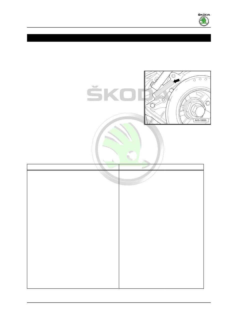
1.1 Engine number
The engine number (“engine identification characters” and “serial
number”) can be found next to the vibration damper -arrow- on
the cylinder block.
In addition, a sticker with the “engine identification characters”
and “serial number” is affixed to the intake manifold.
The engine number consists of up to nine digits (alphanumeric).
The first part represents the “engine code” (a maximum of 3 iden‐
tification letters), the second part the “serial number”. If more than
999.999 engines with the same engine code were produced then
the first digit of the six part section will be replaced by a letter.
Vehicles with four-digit engine identification characters
Four-digit engine identification characters are used. The first 3
digits denote the mechanical design of the engine and are stam‐
ped on the engine as before. The fourth digit refers to the output
and torque of the engine and depends upon the engine control
unit. You can find the four digit engine identification characters on
the vehicle data sticker ⇒ Maintenance ; Booklet Superb II ; ve‐
hicle data sticker and on the engine control unit.
1.2 Engine characteristics
Engine identification characters CDVA
Manufactured 10:08 ►
Exhaust limit values conforming to
EU-4
1)
, EU-5
Displacement
cm
3
3597
Power output kW at rpm 191/6000
Torque Nm at rpm 350/2500-5000
Bore ∅ mm 89.0
Stroke mm 96.35
Cylinder angle 10.6°
Compression ratio 11.4:1
Cylinder / valves per cylinder 6/4
RON
unleaded 98
2)
Ignition system/fuel injection Motronic MED 9.1
Type of fuel preparation Direct injection homoge‐
neous
Knock control 2 sensors
Lambda control 4 Lambda probes
Three-way catalytic converter yes
Exhaust gas recirculation internal
Intake manifold change-over no
Camshaft adjustment yes (inlet and outlet)
Secondary air system no
Exhaust gas turbocharger no
1
) according to EU-5
Superb II 2008 ➤ , Superb II 2011 ➤
3.6/191 kW FSI Engine - Edition 03.2016
1. Technical data 1

Protected by copyright. Copying for private or commercial purposes, in part or in whole, is not permitted
unless authorised by ŠKODA AUTO A. S. ŠKODA AUTO A. S. does not guarantee or accept any liability
with respect to the correctness of information in this document. Copyright by ŠKODA AUTO A. S.�
2)
At least 95 RON in exceptional cases, although engine output
is reduced
Superb II 2008 ➤ , Superb II 2011 ➤
3.6/191 kW FSI Engine - Edition 03.2016
2 Rep. gr.00 - Technical data
Protected by copyright. Copying for private or commercial purposes, in part or in whole, is not permitted
unless authorised by ŠKODA AUTO A. S. ŠKODA AUTO A. S. does not guarantee or accept any liability
with respect to the correctness of information in this document. Copyright by ŠKODA AUTO A. S.�
01 – Self-diagnosis
1 Self diagnosis, safety measures,
cleanliness regulations, directions
1.1 Self-diagnosis
This Rep.-Gr. is deleted.
For this use the “Vehicle self-diagnosis”, “Measuring method” and
“Fault finding” ⇒ Vehicle diagnostic tester.
1.2 Safety precautions when working on
fuel supply system
WARNING
♦ The safety measures for the pressure reduction in the high
pressure system must be observed ⇒ page 4 .
♦ The fuel system is under pressure! Wear safety goggles
and safety clothing, in order to avoid injuries and skin con‐
tact with fuel. Place a clean cleaning cloth around the
connection point before detaching wiring. Reduce pres‐
sure by carefully removing the wiring.
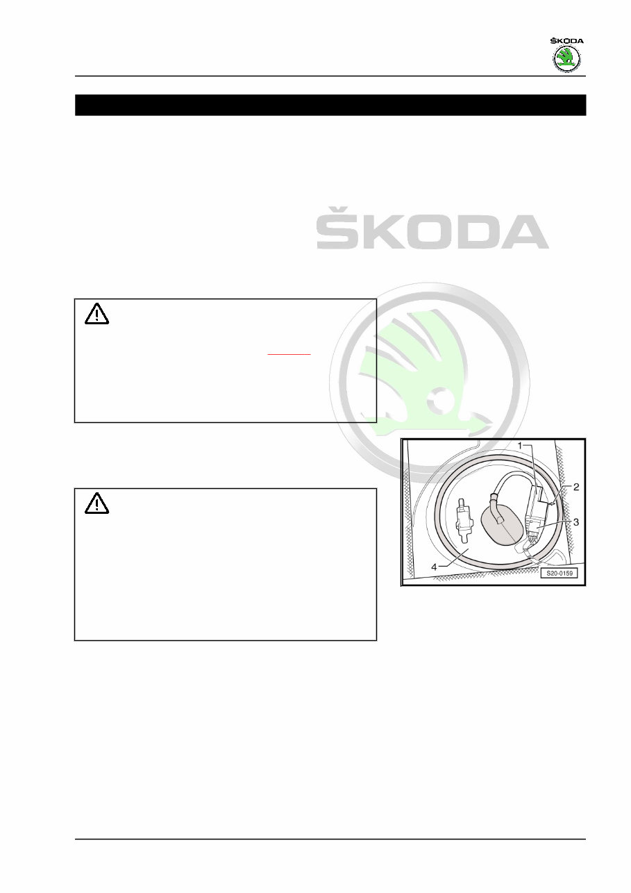
♦ Fuel pump is activated by switching on ignition and via driver
door contact switch. Before opening the fuel system and for
reasons of safety, if the battery is not disconnected, the plug
-3- must be disconnected from the fuel pump control unit.
Caution
When undertaking all assembly work, particularly in the engine
compartment due to its cramped construction, please observe
the following:
♦ Lay lines of all kinds (e.g. for fuel, hydraulic fluid, the active
charcoal container-unit, cooling fluid and refrigerant,
brake fluid, vacuum) and electrical lines in such a way that
the original line guide is re-established.
♦ In order to avoid damage to the cables, ensure that there
is adequate free access to all moving or hot components.
When removing and installing the fuel gauge sender or the fuel
delivery unit from a full or partly filled fuel tank, pay attention to
the following points:
♦ The extraction hose of an exhaust extraction system which is
switched on, must be positioned close to the assembly open‐
ing of the fuel tank in order to extract the released fuel vapours,
even before the work is commenced. If no exhaust extraction
system is available, a radial fan (motor not in air flow of fan)
with a delivery volume of more than 15 m
3
/h must be used.
♦ Avoid skin contact with fuel!
♦ Wear fuel-resistant gloves!
Superb II 2008 ➤ , Superb II 2011 ➤
3.6/191 kW FSI Engine - Edition 03.2016
1. Self diagnosis, safety measures, cleanliness regulations, directions 3
Protected by copyright. Copying for private or commercial purposes, in part or in whole, is not permitted
unless authorised by ŠKODA AUTO A. S. ŠKODA AUTO A. S. does not guarantee or accept any liability
with respect to the correctness of information in this document. Copyright by ŠKODA AUTO A. S.�
1.3 Reduce pressure in the high-pressure
system
WARNING
♦ The injection system consists of a high pressure part
(max. pressure of 12 MPa = 120 bar) and a low pressure
part (pressure of approx. 0.6 MPa = 6 bar).
♦ Before opening the high pressure system, e.g. removing
the high pressure pump, the fuel distributor, the injection
valves, the fuel pipes or the fuel pressure sender - G247
- , the fuel pressure in the high pressure system with a
remaining pressure of approx. 0.6 MPa (6 bar) must be
reduced. The procedure for this is described below.
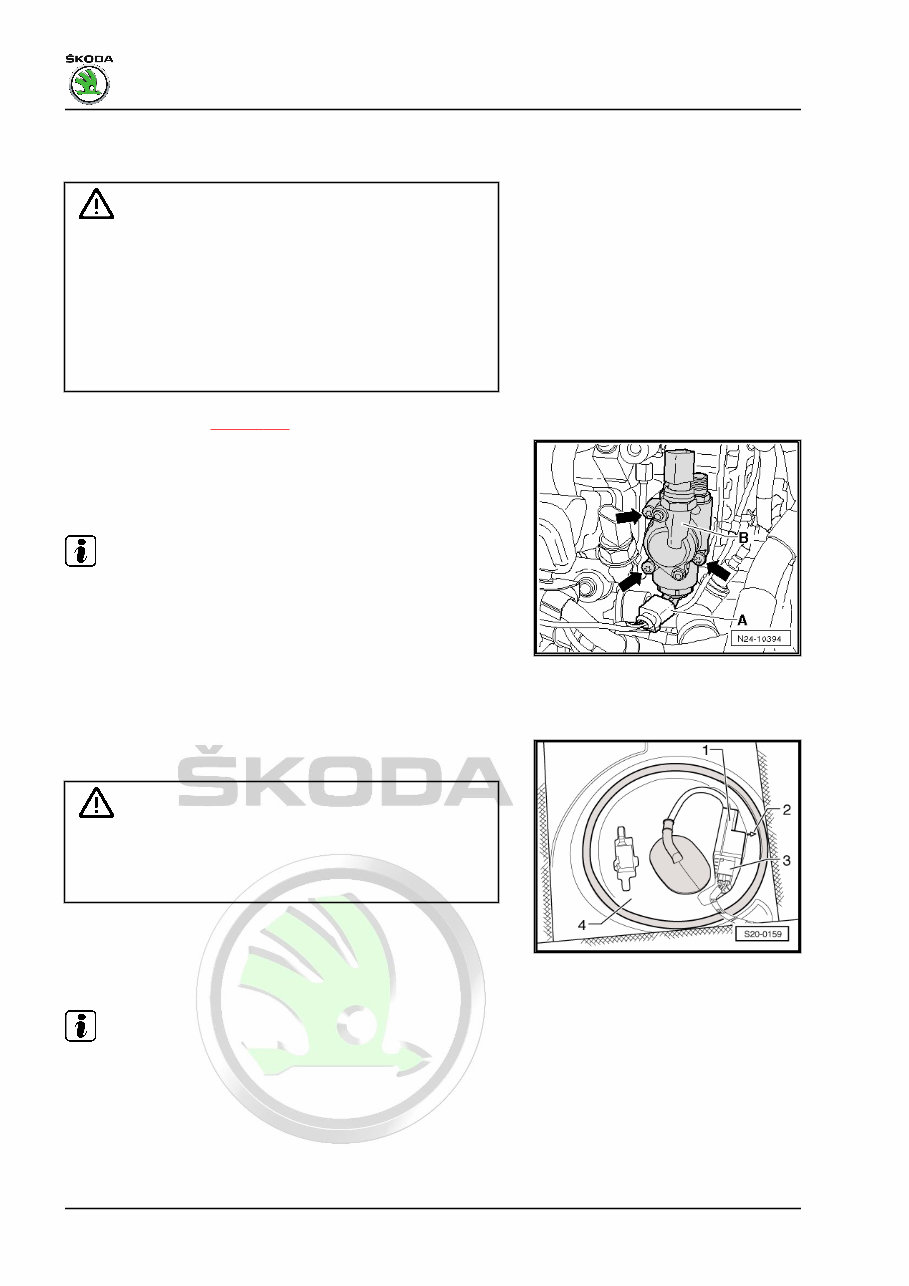
– Remove air guide ⇒ page 180 .
– Disconnect the plug -A- from the fuel pressure regulating valve
- N276- on the high pressure pump using the assembly device
- T10118- .
– Let the engine run at idling speed for approx. 10 seconds.
Note
♦ When the connector is removed from the fuel pressure regu‐
lating valve - N276- in idling mode, the pressure lowers in the
high-pressure part to approx. 0.6 MPa (6 bar).
♦ After high pressure depressurisation, the high-pressure sys‐
tem must be opened as the fuel pressure increases again due
to heating.
– Switch off ignition.
– For safety reasons and before opening the fuel system, dis‐
connect the plug -3- from the fuel pump control unit - J538- .
WARNING
The fuel lines are pressurized! Wear safety goggles and safety
clothing, in order to avoid injuries and skin contact with fuel.
Before opening the high pressure system, lay cleaning cloths
around the connection point.
– Now lay a clean cleaning cloth around the connection point
and carefully open it up, in order to reduce the remaining pres‐
sure of approx 0.6 MPa (6 bar). Collect the fuel which flows
out.
Note
♦ Interrogate the event memory of the engine control unit at the
end of the following work and delete all the event memory en‐
tries.
♦ The readiness code must be generated if the event memory
has been cleared ⇒ Vehicle diagnostic tester.
Superb II 2008 ➤ , Superb II 2011 ➤
3.6/191 kW FSI Engine - Edition 03.2016
4 Rep. gr.01 - Self-diagnosis
You're Reading a Preview
What's Included?
Fast Download Speeds
Offline Viewing
Access Contents & Bookmarks
Full Search Facility
Print one or all pages of your manual
$52.99
Viewed 68 Times Today


Secure transaction
What's Included?
Fast Download Speeds
Offline Viewing
Access Contents & Bookmarks
Full Search Facility
Print one or all pages of your manual
$52.99
2010 SKODA Superb Combi Service & Repair Manual
This comprehensive manual provides detailed information for maintaining and repairing your SKODA Superb Combi. Written in clear, easy-to-follow language, it covers a wide range of topics to help you troubleshoot and repair issues.
- Step-by-step instructions for various repair tasks
- Troubleshooting charts for troubleshooting issues
- Comprehensive diagrams for understanding complex systems
- Detailed illustrations for visual reference
- Torque specifications and special tools required
This manual is suitable for both professional mechanics and DIYers, providing the necessary information to keep your vehicle in excellent condition at an affordable cost. With clear instructions and detailed diagrams, you'll be able to diagnose and repair issues with confidence.
This digital manual is fully printable and compatible with all computers and electronic devices.


