14. Lower the vehicle. 15. Remove the scan tool. 16. Install the tire and wheel assemblies. Refer to Tire and Wheel Removal and Installation . 17. Inspect the brake fluid level. Refer to Master Cylinder Reservoir Filling . 18. Road test the vehicle while inspecting that the pedal remains high and firm. Page 2 of 2 Document ID: 2101448 2/22/2010 http://localhost:9001/si/showDoc.do?docSyskey=2101448&pubCellSyskey=1238&pubObj...
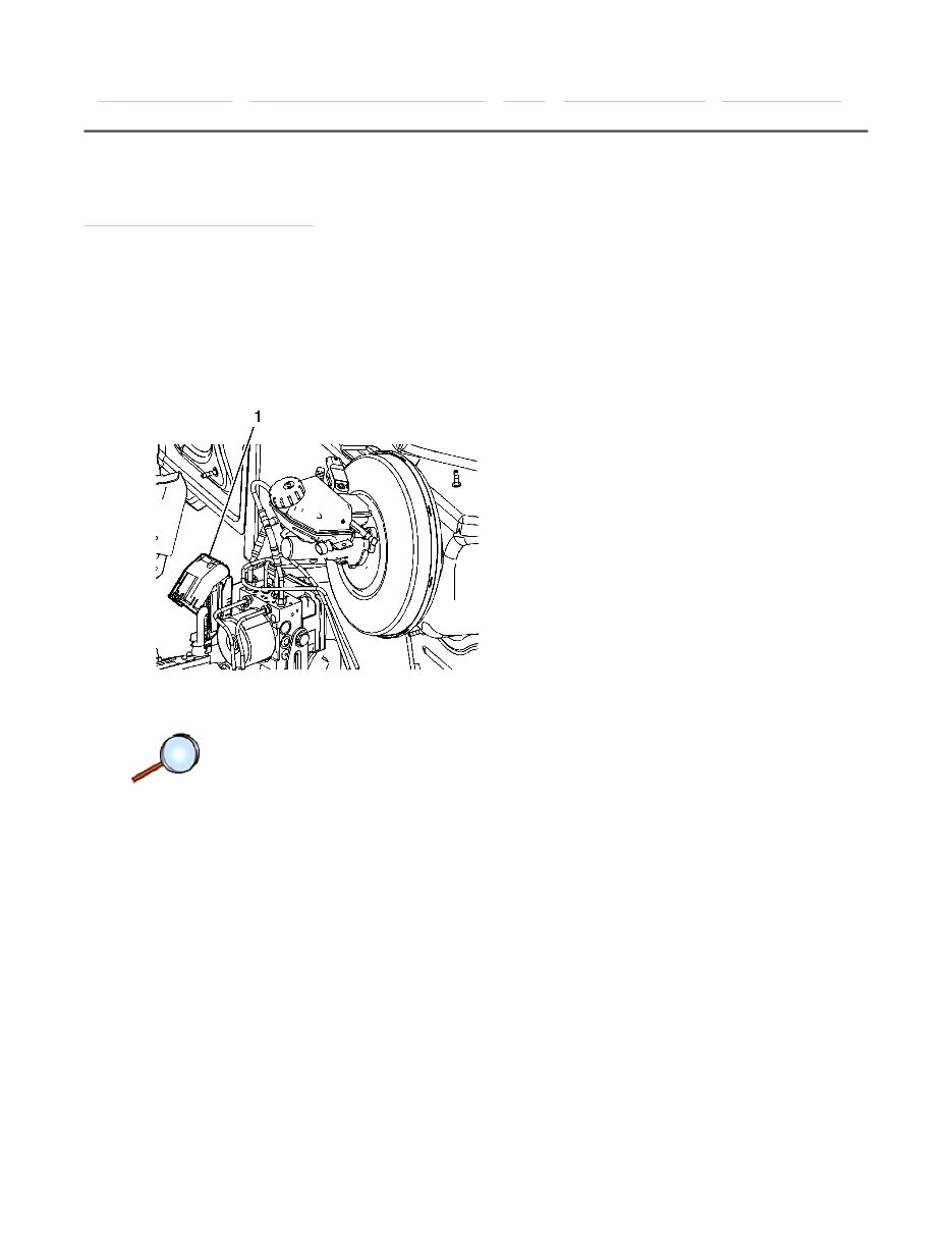
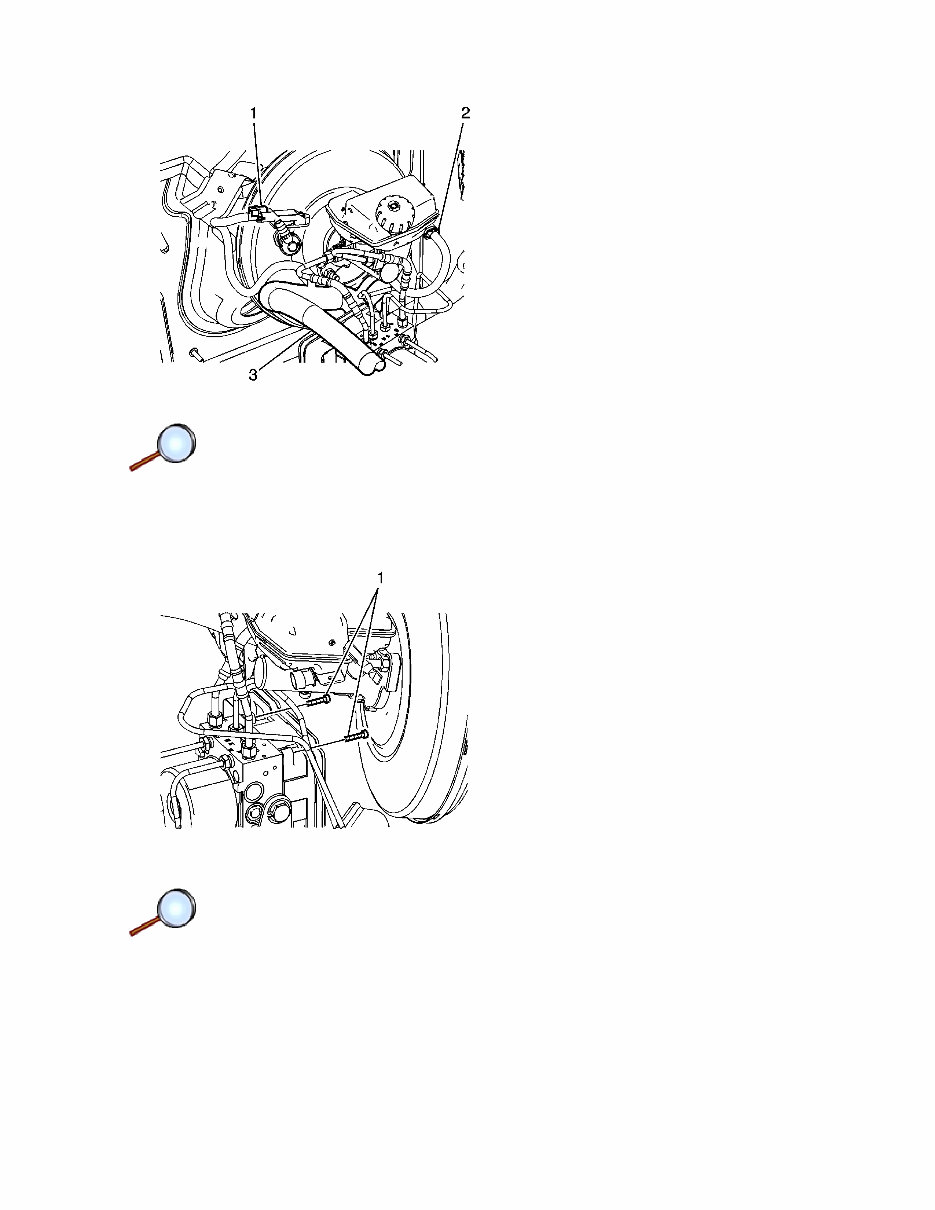
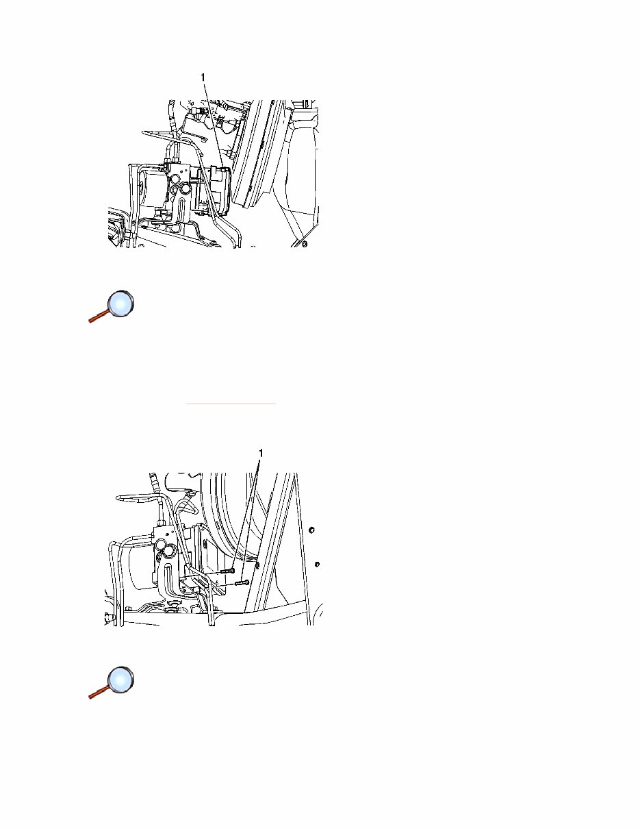
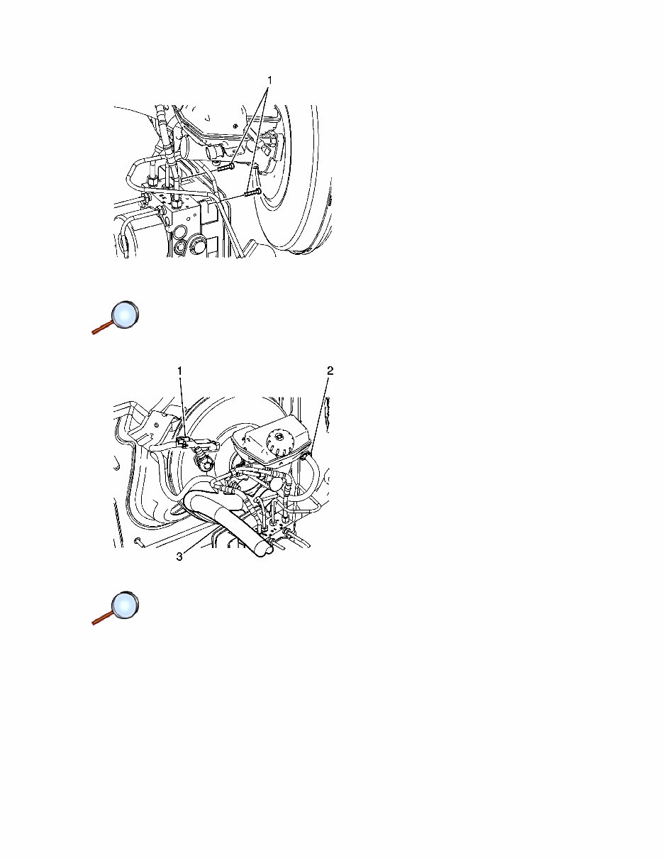
5. Disconnect the power brake booster vacuum sensor electrical connector (1). 6. Disconnect the brake fluid level indicator switch electrical connector (2). 7. Release the engine wiring harness retaining clip from the master cylinder mounting stud and position the harness (3) downward. 8. Remove the 2 upper EBCM bolts (1). Page 2 of 7 Document ID: 2101449 2/22/2010 http://localhost:9001/si/showDoc.do?docSyskey=2101449&pubCellSyskey=954&pubObj...
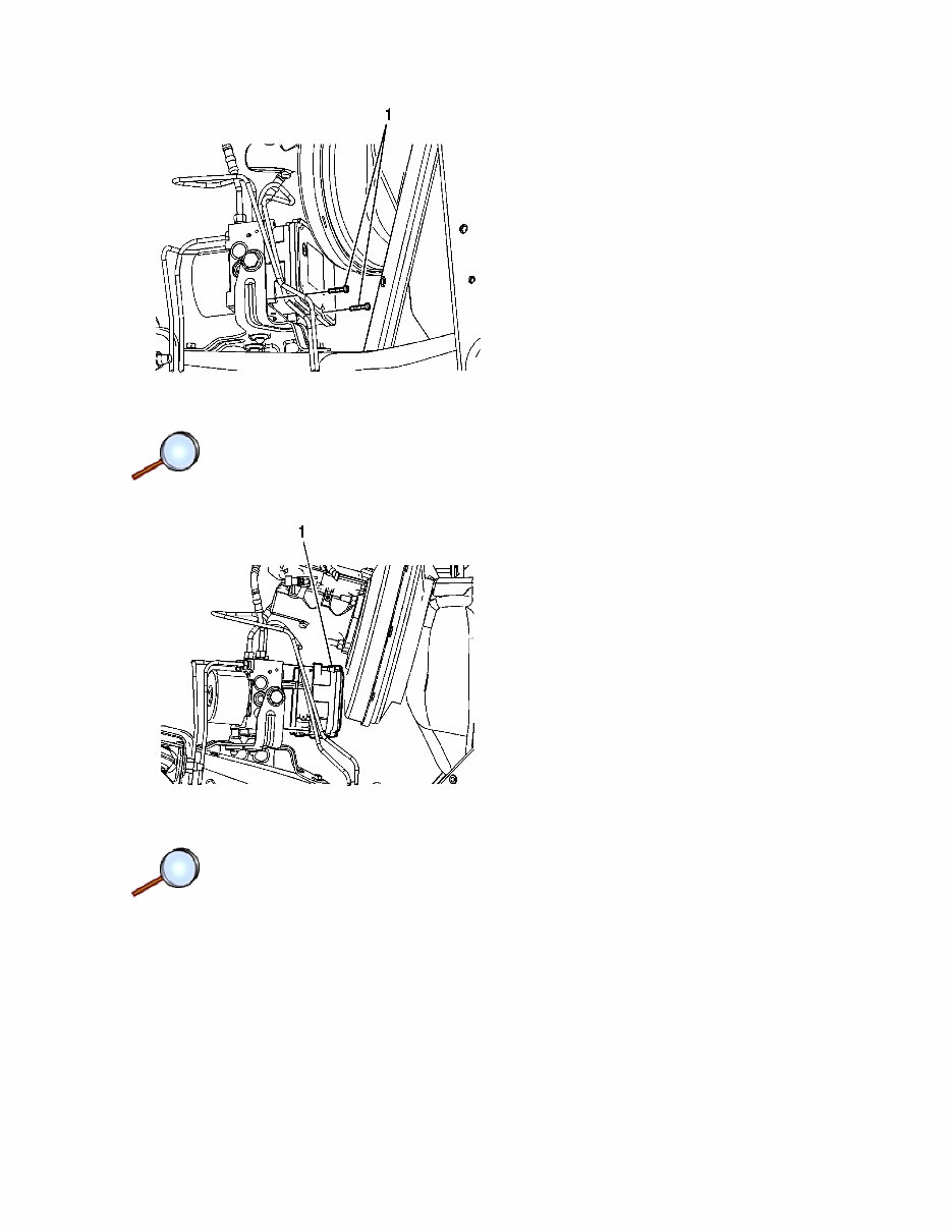
9. Remove the 2 lower EBCM bolts (1). 10. Carefully separate the EBCM (1) from the BPMV. Do not pry the components apart. Page 3 of 7 Document ID: 2101449 2/22/2010 http://localhost:9001/si/showDoc.do?docSyskey=2101449&pubCellSyskey=954&pubObj...
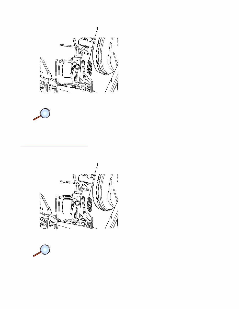
11. If installing a new EBCM, remove the 12 EBCM seals (1). 12. Clean the sealing surface of the BPMV with denatured alcohol and a clean shop cloth and allow to dry. Installation Procedure 1. If installing a new EBCM, install the 12 EBCM seals (1). Page 4 of 7 Document ID: 2101449 2/22/2010 http://localhost:9001/si/showDoc.do?docSyskey=2101449&pubCellSyskey=954&pubObj...
2. While aligning the brake pressure sensor to the BPMV, carefully install the EBCM (1) to the BPMV. Do not force the components together. Caution: Refer to Fastener Caution in the Preface section. 3. Install the 2 lower EBCM bolts (1) and tighten to 2.3 N·m (20 lb in). Page 5 of 7 Document ID: 2101449 2/22/2010 http://localhost:9001/si/showDoc.do?docSyskey=2101449&pubCellSyskey=954&pubObj...
4. Install the 2 upper EBCM bolts (1) and tighten to 2.3 N·m (20 lb in). 5. Position the engine wiring harness upward and connect the power brake booster vacuum sensor electrical connector (1). 6. Connect the brake fluid level indicator switch electrical connector (2). 7. Install the engine wiring harness (3) retaining clip to the master cylinder mounting stud. Page 6 of 7 Document ID: 2101449 2/22/2010 http://localhost:9001/si/showDoc.do?docSyskey=2101449&pubCellSyskey=954&pubObj...
2005-2009 Pontiac Solstice Service & Repair Manual
Thanks for taking the time to look at the 2005-2009 Pontiac Solstice Service & Repair Manual.
This manual covers every service and repair procedure you will need for your Pontiac Solstice. Save yourself BIG money by doing your own repairs with easy-to-follow step-by-step instructions and detailed pictures on all areas of servicing and repairs.
DESCRIPTION:
With this manual, any service or repair job becomes straightforward and stress-free. Detailed explanations, clear illustrations, and practical tips ensure you can perform repairs confidently and correctly. Once purchased, the manual is yours to keep forever – print out one page, an entire chapter, or the full manual. You can also transfer it to your tablet or smart phone as needed.
MODELS COVERED:
Specifically designed for the 2005-2009 Pontiac Solstice. All models, engines, trims, and transmission types are covered.
CONTENTS:
This high quality Service & Repair Manual covers all repair and maintenance procedures A-Z.
Every service and repair procedure is included for comprehensive support.
COMPUTER REQUIREMENTS:
This downloadable manual will work on all PC and MAC computers, tablets, and mobile phones. The only software needed is Adobe Reader, which is typically already installed, or can be downloaded for free.
INSTANT DELIVERY:
Upon receipt of payment by Visa, MasterCard, or PayPal, this manual will be instantly emailed to the address you used at checkout.
Customer Satisfaction Guaranteed.
Recently Viewed
5,521,897Happy Clients
2,594,462eManuals
1,120,453Trusted Sellers
15Years in Business
Price:
Actual Price:
2005-2009 Pontiac Solstice Service & Repair Manual