HAC-1 VENTILATION, HEATER & AIR CONDITIONER C D E F G H J K L M SECTION HAC A B HAC N O P CONTENTS HEATER & AIR CONDITIONING CONTROL SYSTEM AUTOMATIC AIR CONDITIONER BASIC INSPECTION ................................... 4 DIAGNOSIS AND REPAIR WORKFLOW ......... 4 Work Flow ................................................................ 4 INSPECTION AND ADJUSTMENT .................... 5 Description and Conditions ...................................... 5 Operational Check ................................................... 5 Auxiliary Mechanism Trimmers ................................ 6 FUNCTION DIAGNOSIS .............................. 9 FUNCTION INFORMATION ............................... 9 Component Part Location ........................................ 9 Component’s Role .................................................. 11 REFRIGERATION SYSTEM .............................13 Refrigerant Cycle ................................................... 13 Refrigerant System Protection ............................... 13 AUTOMATIC AIR CONDITIONER SYSTEM ....14 System Diagram ..................................................... 14 System Description ................................................ 14 Component Part Location ...................................... 20 Component Description .......................................... 20 DIAGNOSIS SYSTEM (ECM) ............................21 CONSULT-III Function ........................................... 21 SELF-DIAGNOSIS FUNCTION .........................22 Diagnosis Description ............................................ 22 Auxiliary Mechanism Trimmers .............................. 27 COMPONENT DIAGNOSIS ........................ 28 LAN SYSTEM CIRCUIT ....................................28 Description ............................................................. 28 Diagnosis Procedure .............................................. 28 MODE DOOR MOTOR ......................................31 Description ............................................................. 31 Diagnosis Procedure ..............................................32 AIR MIX DOOR MOTOR ................................... 33 Description ..............................................................33 Diagnosis Procedure ..............................................34 INTAKE DOOR MOTOR ................................... 35 Description ..............................................................35 Diagnosis Procedure ..............................................36 BLOWER MOTOR ............................................ 37 Description ..............................................................37 Component Function Check ...................................38 Diagnosis Procedure ..............................................38 MAGNET CLUTCH ........................................... 43 Description ..............................................................43 Component Function Check ...................................43 Diagnosis Procedure ..............................................43 AMBIENT SENSOR .......................................... 47 Description ..............................................................47 Diagnosis Procedure ..............................................47 Component Inspection ............................................48 IN-VEHICLE SENSOR ...................................... 50 Component Description ..........................................50 Diagnosis Procedure ..............................................50 Component Inspection ............................................52 SUNLOAD SENSOR ......................................... 53 Description ..............................................................53 Diagnosis Procedure ..............................................53 Component Inspection ............................................55 INTAKE SENSOR ............................................. 56 Description ..............................................................56 Diagnosis Procedure ..............................................56 Component Inspection ............................................57 POWER SUPPLY AND GROUND CIRCUIT FOR FRONT AIR CONTROL ............................ 58 Description ..............................................................58 Revision: September 2009 2010 Altima
HAC-2 Component Function Check .................................. 58 Diagnosis Procedure ............................................. 58 ECU DIAGNOSIS ....................................... 60 AIR CONDITIONER CONTROL ....................... 60 Reference Value .................................................... 60 WIRING DIAGRAM .................................... 62 AIR CONDITIONER CONTROL ....................... 62 COUPE ..................................................................... 62 COUPE : Wiring Diagram - Air Conditioner Control (Auto) - Coupe ....................................................... 62 SEDAN ..................................................................... 71 SEDAN : Wiring Diagram - Air Conditioner Control (Auto) - Sedan ....................................................... 72 SYMPTOM DIAGNOSIS ............................ 82 AIR CONDITIONER CONTROL ....................... 82 Symptom Matrix Chart ......................................... 82 INSUFFICIENT COOLING ................................ 83 Component Function Check .................................. 83 Diagnostic Work Flow ............................................ 84 Performance Chart ................................................ 86 Trouble Diagnosis For Abnormal Pressure ............ 87 INSUFFICIENT HEATING ................................ 91 Component Function Check .................................. 91 NOISE ............................................................... 93 Component Function Check .................................. 93 SELF-DIAGNOSIS CANNOT BE PER- FORMED ........................................................... 95 Diagnosis Procedure ............................................. 95 MEMORY FUNCTION DOES NOT OPERATE ... 96 Diagnosis Procedure ............................................. 96 PRECAUTION ............................................ 97 PRECAUTIONS ................................................ 97 Precaution for Supplemental Restraint System (SRS) "AIR BAG" and "SEAT BELT PRE-TEN- SIONER" ................................................................ 97 Working with HFC-134a (R-134a) ......................... 97 Precaution for Service Equipment ......................... 98 MANUAL AIR CONDITIONER BASIC INSPECTION .................................. 99 DIAGNOSIS AND REPAIR WORKFLOW ........ 99 Work Flow .............................................................. 99 INSPECTION AND ADJUSTMENT ................ 100 Description & Conditions ...................................... 100 Operational Check ................................................ 100 FUNCTION DIAGNOSIS ........................... 102 FUNCTION INFORMATION ............................ 102 Component Part Location .................................... 102 Component’s Role ............................................... 104 AIR CONDITIONER CONTROL ...................... 105 System Diagram .................................................. 105 System Description .............................................. 105 Component Part Location .................................... 111 Component Description ....................................... 111 DIAGNOSIS SYSTEM (ECM) .......................... 112 CONSULT-III Function ......................................... 112 COMPONENT DIAGNOSIS ...................... 113 LAN SYSTEM CIRCUIT .................................. 113 Description ........................................................... 113 Diagnosis Procedure ............................................ 113 MODE DOOR MOTOR .................................... 116 Description ........................................................... 116 Diagnosis Procedure ............................................ 117 AIR MIX DOOR MOTOR ................................. 118 Description ........................................................... 118 Diagnosis Procedure ............................................ 119 INTAKE DOOR MOTOR .................................. 120 Description ........................................................... 120 Diagnosis Procedure ............................................ 120 BLOWER MOTOR ........................................... 122 Description ........................................................... 122 Component Function Check ................................ 122 Diagnosis Procedure ............................................ 122 MAGNET CLUTCH .......................................... 127 Component Function Check ................................ 127 Diagnosis Procedure ............................................ 127 POWER SUPPLY AND GROUND CIRCUIT FOR FRONT AIR CONTROL .......................... 130 Description ........................................................... 130 Component Function Check ................................ 130 Diagnosis Procedure ............................................ 130 ECU DIAGNOSIS ...................................... 132 AIR CONDITIONER CONTROL ...................... 132 Reference Value .................................................. 132 WIRING DIAGRAM ................................... 134 AIR CONDITIONER CONTROL ...................... 134 COUPE ................................................................... 134 COUPE : Wiring Diagram - Air Conditioner Control (Manual) - Coupe ................................................. 134 SEDAN ................................................................... 141 Revision: September 2009 2010 Altima
HAC-3 C D E F G H J K L M A B HAC N O P SEDAN : Wiring Diagram - Air Conditioner Control (Manual) - Sedan ................................................. 142 SYMPTOM DIAGNOSIS ........................... 150 AIR CONDITIONER CONTROL ...................... 150 Symptom Matrix Chart ........................................ 150 INSUFFICIENT COOLING .............................. 151 Component Function Check ................................. 151 Diagnostic Work Flow .......................................... 152 Performance Chart ............................................... 154 Trouble Diagnosis For Abnormal Pressure .......... 155 INSUFFICIENT HEATING ............................... 159 Component Function Check ................................. 159 NOISE .............................................................. 161 Component Function Check ................................. 161 PRECAUTION ........................................... 163 PRECAUTIONS ............................................... 163 Precaution for Supplemental Restraint System (SRS) "AIR BAG" and "SEAT BELT PRE-TEN- SIONER" .............................................................. 163 Working with HFC-134a (R-134a) ........................ 163 Precaution for Service Equipment ........................ 164 Revision: September 2009 2010 Altima
HAC-4 < BASIC INSPECTION > [AUTOMATIC AIR CONDITIONER] DIAGNOSIS AND REPAIR WORKFLOW BASIC INSPECTION DIAGNOSIS AND REPAIR WORKFLOW Work Flow INFOID:0000000005432601 DETAILED FLOW 1.LISTEN TO CUSTOMER COMPLAINT Listen to customer complaint. Get detailed information about the conditions and environment when the symp- tom occurs. >> GO TO 2 2.VERIFY THE SYMPTOM WITH OPERATIONAL CHECK Verify the symptom with operational check. Refer to HAC-5, "Description and Conditions" . >> GO TO 3 3.GO TO APPROPRIATE TROUBLE DIAGNOSIS Go to appropriate trouble diagnosis. Refer to HAC-82, "Symptom Matrix Chart" . >> GO TO 4 4.REPAIR OR REPLACE Repair or replace the specific parts. >> GO TO 5 5.FINAL CHECK Final check. Is the inspection result normal? YES >> Inspection End. NO >> GO TO 3 Revision: September 2009 2010 Altima
INSPECTION AND ADJUSTMENT HAC-5 < BASIC INSPECTION > [AUTOMATIC AIR CONDITIONER] C D E F G H J K L M A B HAC N O P INSPECTION AND ADJUSTMENT Description and Conditions INFOID:0000000005432602 DESCRIPTION The purpose of the operational check is to confirm that the system operates properly. CONDITIONS: • Engine running and at normal operation temperature. Operational Check INFOID:0000000005432603 STEP 1: Check Blower 1. Turn blower control dial clockwise, blower should operate on low speed. 2. Continue turning blower control dial clockwise, and continue checking blower speeds until all speeds are checked. 3. Leave blower on HI speed. If NG, go to HAC-38, "Diagnosis Procedure" . If OK, continue with next check. STEP 2: Check Discharge Air 1. Press each mode switch and press DEF ( ) switch. 2. Each mode position indicator should illuminate. 3. Confirm that discharge air comes out according to the air distribution table. Refer to HAC-14, "System Description" . NOTE: Confirm that the compressor clutch is engaged (audio or visual inspection) and intake door is in the FRE ( ) position when the DEF ( ) is selected. Intake door position is checked in the next step. If NG, go to HAC-32, "Diagnosis Procedure" . If OK, continue with next check. STEP 3: Check Recirculation 1. Press REC ( ) switch. Recirculation indicator should illuminate. 2. Press REC ( ) switch a second time. 3. Listen for intake door position change (you should hear blower sound change slightly). If NG, go to HAC-34, "Diagnosis Procedure" . If OK, continue with next check. STEP 4: Check Temperature Decrease 1. Turn the temperature dial counterclockwise to 18°C (60F°). 2. Check for cold air at discharge air outlets. If NG, go to HAC-83, "Component Function Check" . If OK, continue with next check. STEP 5: Check Temperature Increase 1. Turn the temperature dial clockwise to 32°C (90°F). 2. Check for hot air at discharge air outlets. If NG, go to HAC-91, "Component Function Check" . If OK, continue with next check. STEP 6: Check AUTO Mode 1. Press the AUTO switch. Revision: September 2009 2010 Altima
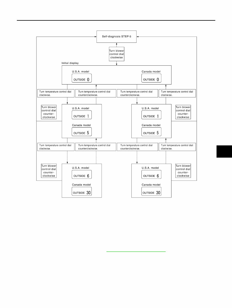
HAC-6 < BASIC INSPECTION > [AUTOMATIC AIR CONDITIONER] INSPECTION AND ADJUSTMENT 2. Confirm that the compressor clutch engages (audio or visual inspection). (Discharge air and blower speed will depend on ambient, in-vehicle and set temperatures.) If NG, go to HAC-58, "Diagnosis Procedure" . If all operational checks are OK (symptom can not be duplicated), refer to GI-37, "Work Flow" and perform tests as outlined to simulate driving conditions environment. If symptom appears, refer to HAC-82, "Symptom Matrix Chart" . Auxiliary Mechanism Trimmers INFOID:0000000005432604 TEMPERATURE SETTING TRIMMER The trimmer compensates for differences in range of ±3°C (±6°F) between temperature setting (displayed dig- itally) and temperature felt by customer. Operating procedures for this trimmer are as follows: 1. Begin self-diagnosis STEP-5 mode. Refer to HAC-22, "Diagnosis Description" . 2. Turn blower control dial clockwise to set system in auxiliary mode. 3. Display shows “61” in auxiliary mechanism. It takes approximately 3 seconds to enable setting operation. 4. Turn temperature control dial (LH) as desired. Temperature will change at a rate of 0.5°C (1.0°F) each time a dial is turned. NOTE: • A decimal point is not indicated on the display. Revision: September 2009 2010 Altima
INSPECTION AND ADJUSTMENT HAC-7 < BASIC INSPECTION > [AUTOMATIC AIR CONDITIONER] C D E F G H J K L M A B HAC N O P • Negative value is displayed on the LH temperature display. When battery cable is disconnected or battery voltage is below 10 V, trimmer operation is canceled. Tempera- ture set becomes that of initial condition, i.e. 0°C (0°F). FOOT POSITION SETTING TRIMMER D/F1 stop position mode can be set. Operating procedures for this trimmer are as follows: 1. Begin self-diagnosis STEP-5 mode. Refer to HAC-22, "Diagnosis Description" . 2. Turn blower control dial clockwise to set system in auxiliary mode. 3. Press the OFF switch for each mode as desired. AWIIA0610GB Revision: September 2009 2010 Altima
HAC-8 < BASIC INSPECTION > [AUTOMATIC AIR CONDITIONER] INSPECTION AND ADJUSTMENT When battery cable is disconnected or battery voltage is below 10 V, trimmer operation is canceled. Foot posi- tion mode set becomes that of initial condition. INLET PORT MEMORY FUNCTION When ignition switch is turned from OFF to ON, inlet port can be set to AUTO or manual. Operating procedures for this trimmer are as follows: 1. Begin self-diagnosis STEP-5 mode. Refer to HAC-22, "Diagnosis Description" . 2. Turn blower control dial clockwise to set system in auxiliary mode. 3. Press REC ( ) switch as desired. When battery cable is disconnected or battery voltage is below 10 V, memory function is canceled. Memory function set becomes that of initial condition. MODE Stop Position AUTO D/F1 Manual D/F1 Blower speed display DEF door DEF door 1st speed D/F1 OPEN FOOT CLOSED 2nd speed D/F1 OPEN D/F1 OPEN 3rd speed FOOT CLOSED D/F1 OPEN 4th speed FOOT CLOSED FOOT CLOSED LED status of REC ( ) position LED status of DEF ( ) position Setting status REC ( ) FRE ( ) ON ON Memorized Memorized ON OFF Memorized (initial state) Not memorized (AUTO control) (initial state) OFF ON Not memorized (AUTO control) Memorized OFF OFF Not memorized (AUTO control) Not memorized (AUTO control) Revision: September 2009 2010 Altima
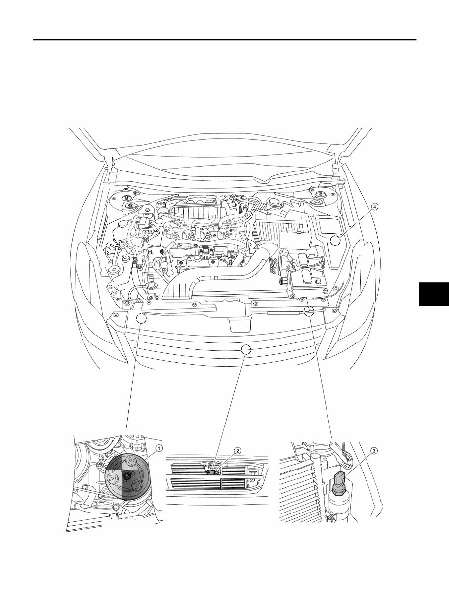
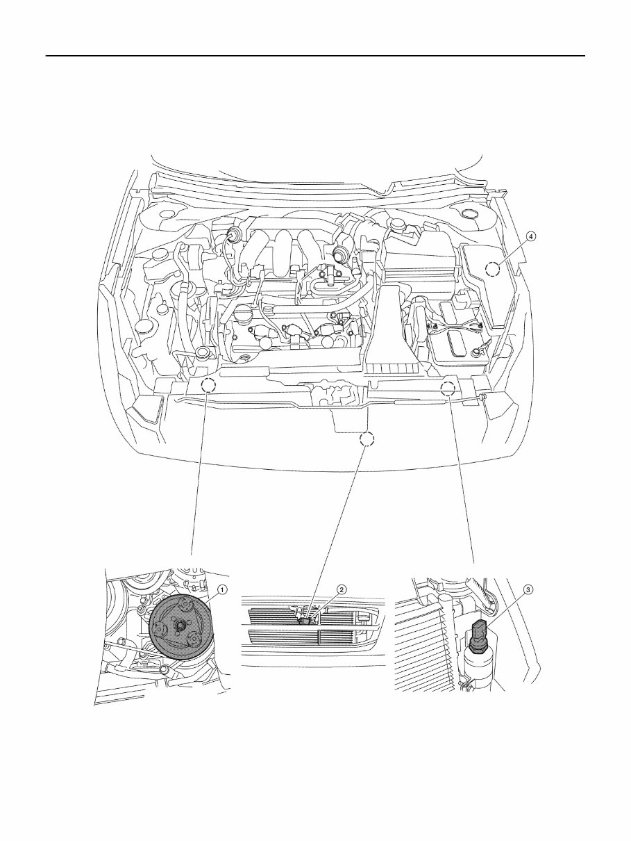
FUNCTION INFORMATION HAC-9 < FUNCTION DIAGNOSIS > [AUTOMATIC AIR CONDITIONER] C D E F G H J K L M A B HAC N O P FUNCTION DIAGNOSIS FUNCTION INFORMATION Component Part Location INFOID:0000000005432605 ENGINE COMPARTMENT QR25DE Models AWIIA1236ZZ Revision: September 2009 2010 Altima
HAC-10 < FUNCTION DIAGNOSIS > [AUTOMATIC AIR CONDITIONER] FUNCTION INFORMATION VQ35DE Models 1. A/C compressor F3 2. Ambient sensor E211 (sedan loca- tion shown, Coupe location similar) 3. Refrigerant pressure sensor E219 4. A/C relay (internal to IPDM E/R) AWIIA1237ZZ Revision: September 2009 2010 Altima
If you are in need of a repair manual for your 2010 Nissan Altima, look no further. This comprehensive manual is suitable for both professional mechanics and DIY enthusiasts. In the past, traditional paper manuals were the norm, but now you can access all the necessary information in a more convenient digital format.
Whether you are looking to address brake issues, replace suspension components, troubleshoot engine problems, or perform standard maintenance, this manual has got you covered. It contains detailed service information for various vehicle systems including brakes, engine, suspension, steering, drivetrain, electrical, heating, and air conditioning.
By utilizing this manual, you can save a significant amount of money on repairs. Professional mechanics often charge high fees for their services, making a DIY approach a cost-effective alternative. The manual is compatible with Windows, Mac computers, smartphones, and tablets, ensuring ease of access for all users.