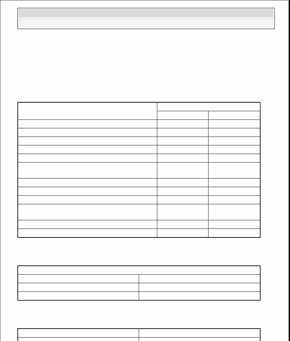
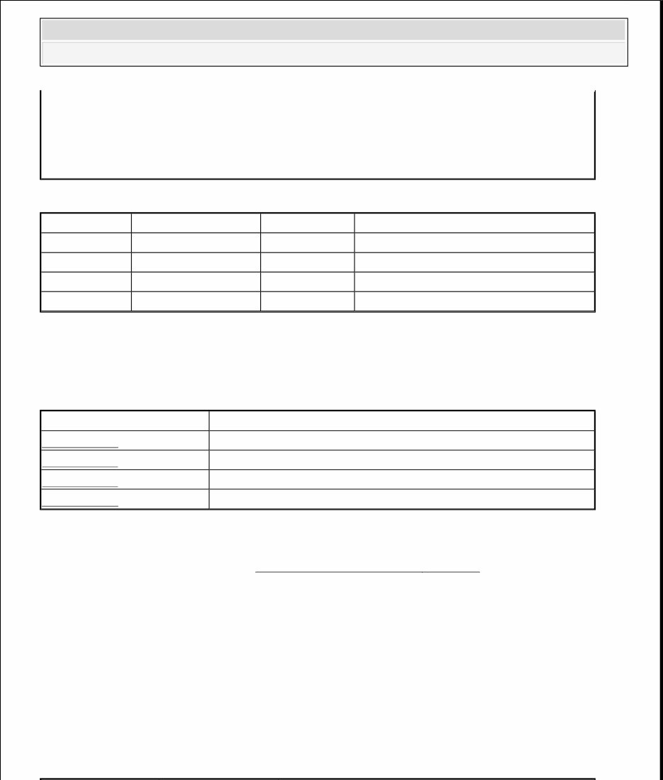
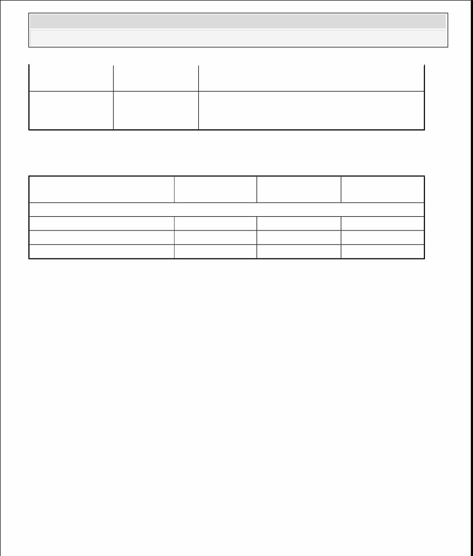
2006 ENGINE Engine Electrical - H3 SPECIFICATIONS FASTENER TIGHTENING SPECIFICATIONS Fastener Tightening Specifications BATTERY USAGE Battery Usage GENERATOR USAGE Generator Usage Application Specification Metric English Air Conditioning Compressor Bolt 50 N.m 37 lb ft Battery Cable to Battery Nut 9 N.m 80 lb in Battery Retainer Nut 15 N.m 11 lb ft Generator Mounting Bolt 50 N.m 37 lb ft Generator Output BAT Terminal Nut 20 N.m 15 lb ft Generator Positive Cable to Underhood Fuse Block Nut 9 N.m 80 lb in Negative Battery Cable to Battery Tray Bolt 9 N.m 80 lb in Negative Battery Cable to Engine Block Bolt 35 N.m 26 lb ft Positive Battery Cable to Starter Terminal Nut 9 N.m 80 lb in Positive Battery Cable to Underhood Fuse Block Nut 9 N.m 80 lb in Starter Motor Bolt/Nut 50 N.m 37 lb ft Starter Solenoid S Terminal Nut 3.5 N.m 31 lb in Base Cold Cranking Amperage (CCA) 690 A Reserve Capacity Rating 90 Minutes Replacement Battery Number 78-6YR Generator Model Valeo 2006 Hummer H3 2006 ENGINE Engine Electrical - H3 2006 Hummer H3 2006 ENGINE Engine Electrical - H3
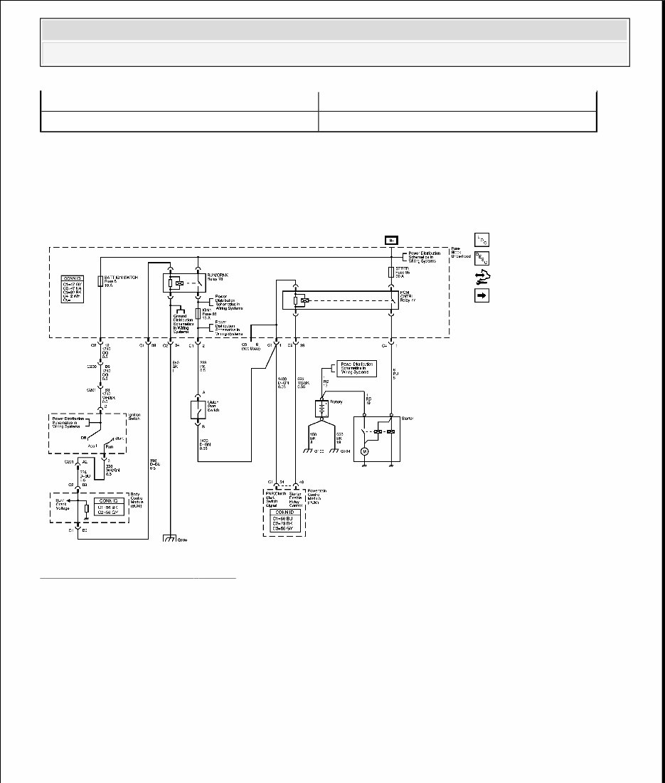
SCHEMATIC AND ROUTING DIAGRAMS STARTING AND CHARGING SCHEMATICS Fig. 1: Starting System - MA5 Courtesy of GENERAL MOTORS CORP. Rated Output 100 A Load Test Output 70 A 2006 Hummer H3 2006 ENGINE Engine Electrical - H3
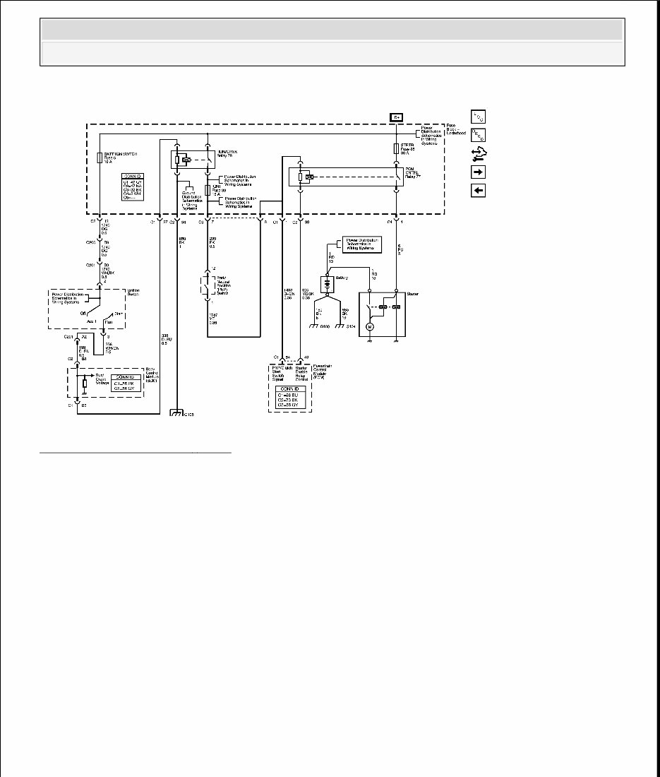
Fig. 2: Starting System - M30 Courtesy of GENERAL MOTORS CORP. 2006 Hummer H3 2006 ENGINE Engine Electrical - H3
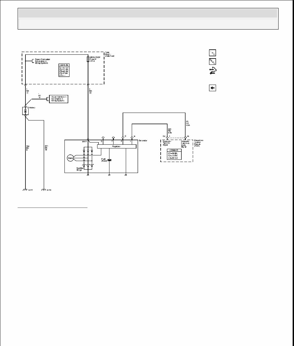
Fig. 3: Charging System Courtesy of GENERAL MOTORS CORP. COMPONENT LOCATOR ENGINE ELECTRICAL COMPONENT VIEWS 2006 Hummer H3 2006 ENGINE Engine Electrical - H3
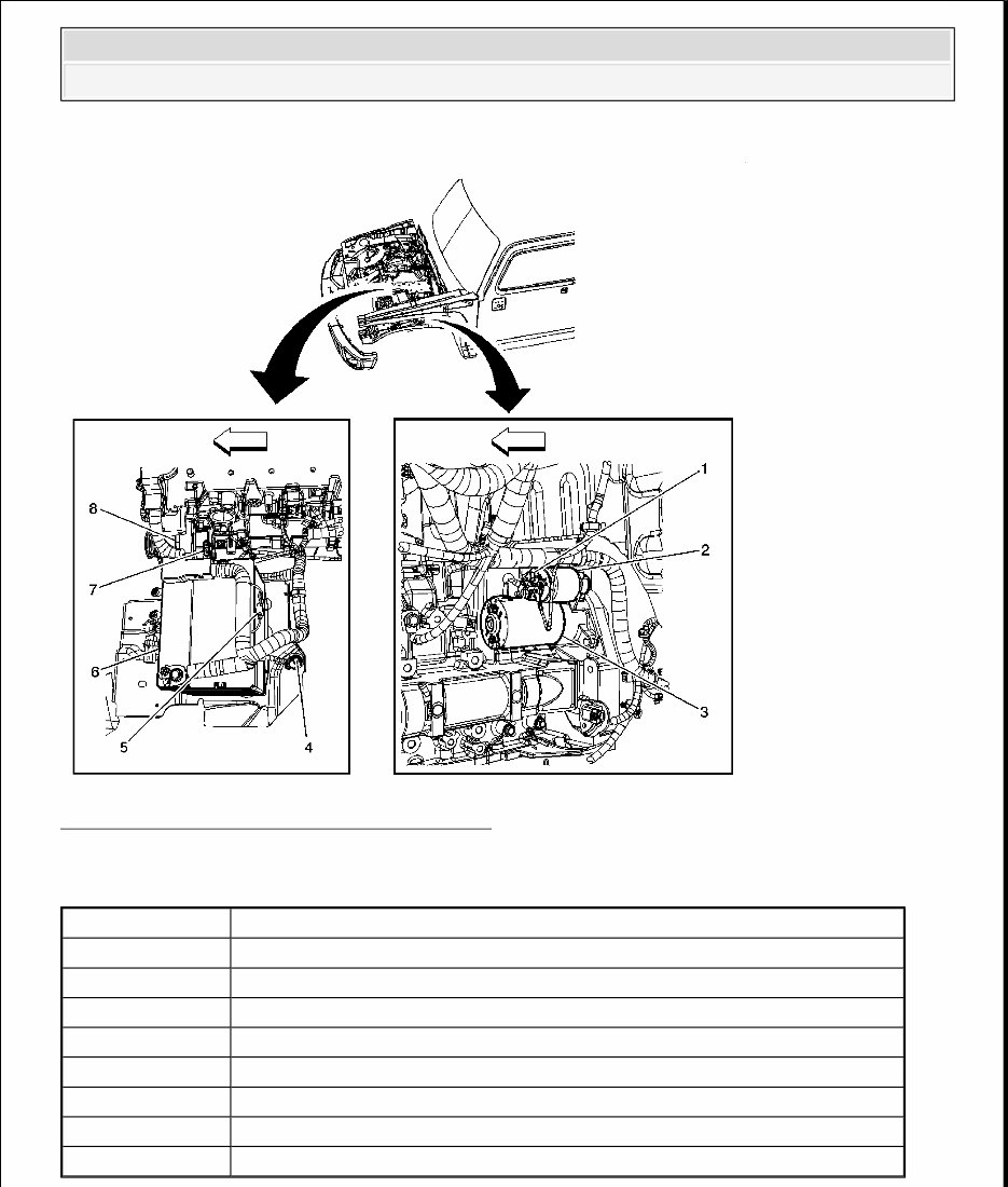
Fig. 4: Engine Electrical Components 1 of 2 Courtesy of GENERAL MOTORS CORP. Callouts For Fig. 4 Callout Component Name 1 Battery Positive Voltage 2 Starter Solenoid 3 Starter Crank Voltage 4 Starter Motor 5 G100 6 Battery 7 Generator Connector 8 Generator 2006 Hummer H3 2006 ENGINE Engine Electrical - H3
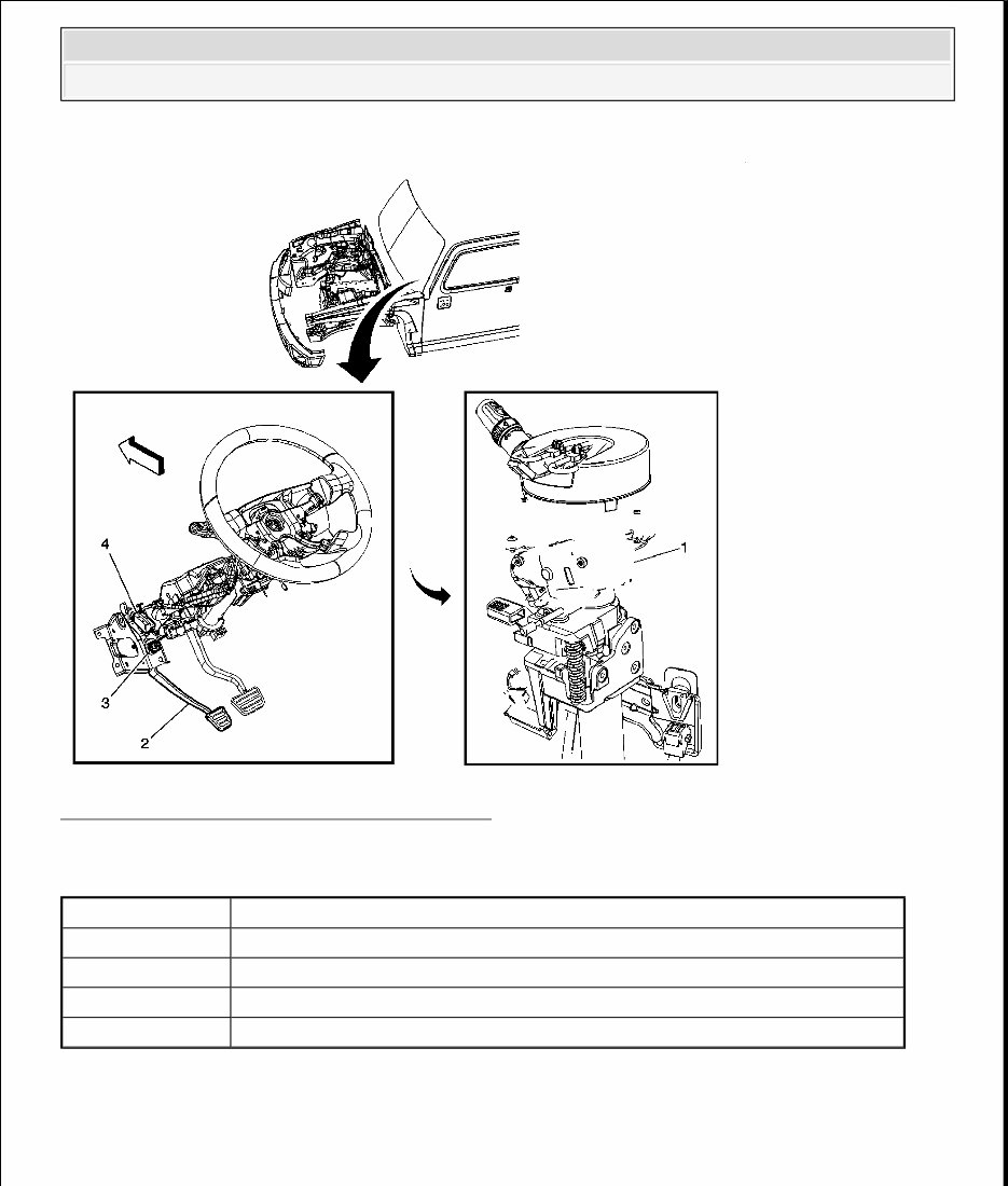
Fig. 5: Engine Electrical Components 2 of 2 Courtesy of GENERAL MOTORS CORP. Callouts For Fig. 5 ENGINE ELECTRICAL CONNECTOR END VIEWS Clutch Start Switch Callout Component Name 1 Ignition Switch 2 Clutch Pedal (MA5) 3 Clutch Release Switch (MA5) 4 Clutch Start Switch (MA5) 2006 Hummer H3 2006 ENGINE Engine Electrical - H3
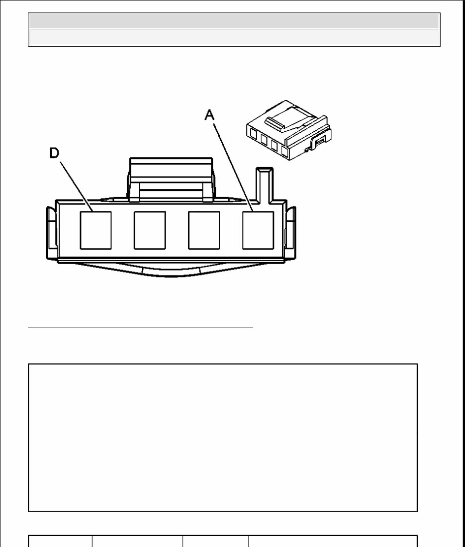
Fig. 6: Clutch Start Switch Connector End Views Courtesy of GENERAL MOTORS CORP. Clutch Start Switch Connector Parts Information Clutch Start Switch Connector Terminal Identification Connector Part Information OEM: 12033706 Service: 15306359 Description: 4-Way F Metri-Pack 280 (BU) Terminal Part Information Pins: Terminal: 12034046/2 Core/Insulation Crimp: Release Tool/Test Probe: 12094430/J-35616-4A (PU) 2006 Hummer H3 2006 ENGINE Engine Electrical - H3
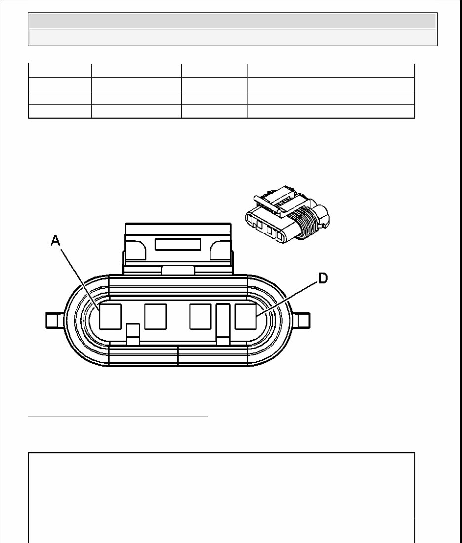
Generator Fig. 7: Generator Connector End Views Courtesy of GENERAL MOTORS CORP. Generator Connector Parts Information Pin Wire Color Circuit No. Function A PK 239 Run/Crank Ignition 1 Voltage B D-GN 1433 Clutch Start Switch Signal C-D - - Not Used Connector Part Information OEM: 12186568 Service: See Catalog Description: 4-Way F Metri-Pack 150 Sealed (BK) Terminal Part Information 2006 Hummer H3 2006 ENGINE Engine Electrical - H3
Generator Connector Terminal Identification DIAGNOSTIC INFORMATION AND PROCEDURES DIAGNOSTIC CODE INDEX DIAGNOSTIC CODE INDEX DIAGNOSTIC STARTING POINT - ENGINE ELECTRICAL Begin the system diagnosis with the Diagnostic System Check - Vehicle in Vehicle DTC Information. The Diagnostic System Check will provide the following information: The identification of the control modules which command the system The ability of the control modules to communicate through the serial data circuit The identification of any stored DTCs and their status The use of the Diagnostic System Check will identify the correct procedure for diagnosing the system and where the procedure is located. SCAN TOOL OUTPUT CONTROLS Powertrain Control Module Pins: Terminal: Core/Insulation Crimp: Release Tool/Test Probe: Pin Wire Color Circuit No. Function A - - Not Available B RD 225 Generator Turn On Signal C GY 23 Generator Field Duty Cycle Signal D - - Not Available DTC Description DTC P0562 System Voltage Low DTC P0563 System Voltage High DTC P0621 Generator L-Terminal Circuit DTC P0622 Generator F-Terimal Circuit 2006 Hummer H3 2006 ENGINE Engine Electrical - H3
SCAN TOOL DATA LIST Powertrain Control Module (PCM) SCAN TOOL DATA DEFINITIONS Generator L Terminal Signal The scan tool displays OK/No Output. The scan tool displays OK until malfunction is detected on the generator L terminal circuit, then it reads No Output. Generator F Terminal Signal The scan tool displays 0-100 percent. The scan tool displays 0-5 percent until the engine is running, then the percentage value varies depending on electrical loads. Ignition 1 Signal The scan tool displays system voltage received by the module. DTC P0562 Circuit Description The powertrain control module (PCM) monitors the system voltage to make sure that the voltage stays within the proper range. If the PCM detects an excessively low system voltage, DTC P0562 will set. When the charging system detects a fault, the instrument panel cluster (IPC) displays a message or Scan Tool Output Control Additional Menu Selection(s) Description GEN L Terminal - The PCM commands the generator Off when you select Off. The Generator will stop generating an output voltage. Scan Tool Parameter Data List Units Displayed Typical Data Value Ignition ON/Engine OFF Generator L Terminal Signal Engine 2 OK/No Output OK Generator F Terminal Signal Engine 2 % 10 - 90% Ignition 1 Signal Engine 1,2,3 volts 9.6 - 14.4v 2006 Hummer H3 2006 ENGINE Engine Electrical - H3
If you are in need of a repair manual for your 2006 Hummer H3, look no further. This comprehensive manual is designed to assist both professional mechanics and DIY enthusiasts in maintaining and repairing their vehicles.
Gone are the days of traditional paper manuals. This accessible digital manual provides all the necessary information in a convenient format, making it more affordable and easier to use.
Whether you are looking to address brake issues, replace suspension components, troubleshoot engine problems, or perform standard maintenance, this manual has you covered. It includes detailed service information for brakes, engine, suspension, steering, drivetrain, electrical systems, heating, air conditioning, and more.
By utilizing this manual, you can save a significant amount of money on repairs. Professional mechanics often charge high fees for their services, making a DIY approach with the help of this manual a cost-effective alternative.
This manual is compatible with Windows, Mac computers, smartphones, and tablets, ensuring ease of access for all users.