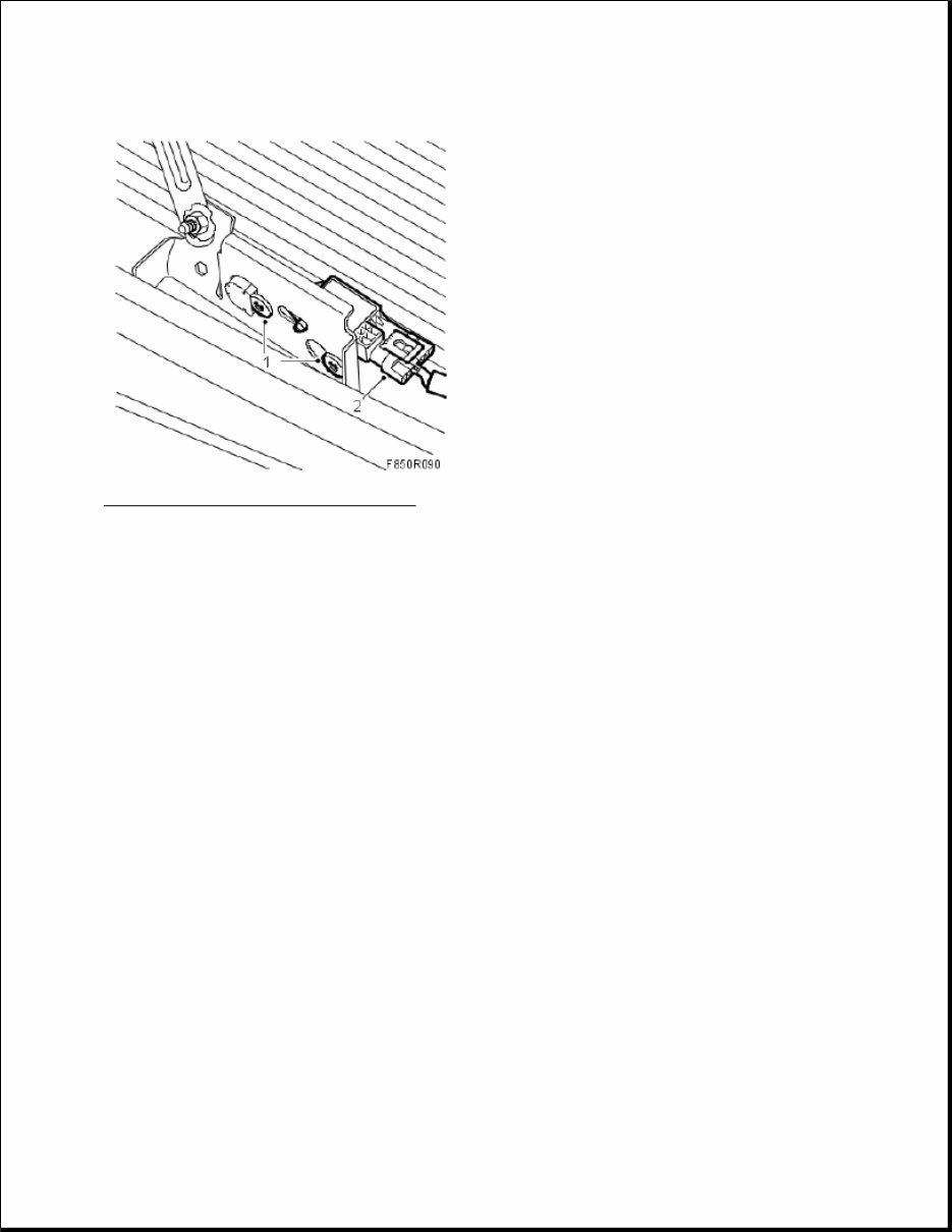
Fig. 100: Illustration For Steps 1 And 2 Courtesy of SAAB-SCANIA OF AMERICA, INC. Tightening torque 9 Nm (7 lbf ft) 2. Connect the impact sensor's connector. 3. Fit the front bumper casing. 4. Connect the battery. 5. Turn ON the ignition and check the airbag system and control module using the diagnostic tool as follows: Connect the diagnostic tool to the data link connector under the dashboard. Delete any diagnostic trouble codes. Turn the ignition OFF and then ON again. Wait at least 1 minute with the ignition on. Check whether a diagnostic trouble code is displayed: If a diagnostic trouble code is displayed: Carry out fault diagnosis according to the instructions under respective trouble codes. If no diagnostic trouble code is displayed: Fitting completed correctly. Disconnect the diagnostics instrument. 6. Carry out Measures after disconnecting the battery. IMPACT SENSOR, SIDE, FRONT (328D, 328P)
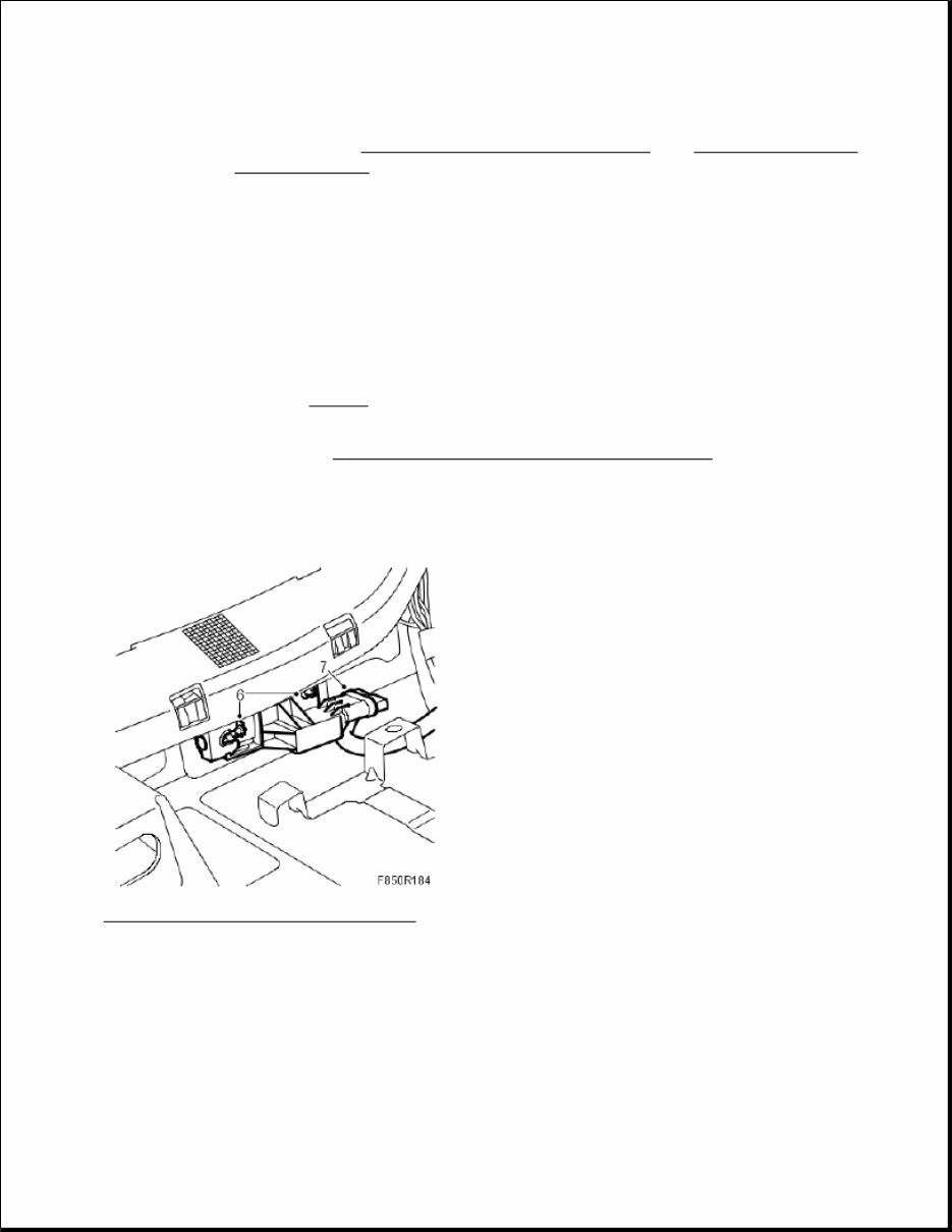
To remove 1. Turn the ignition key to the position LOCK. 2. Remove the front seat. See SEATS . 3. Dismantle the front and rear scuff plates. 4. Remove the B-pillar trim. See B - PILLAR, SPARE PART, COMPLETE SIDE . 5. Fold under the carpet. 6. Dismantle the side impact sensor by loosening the screws a few turns. Press together the locking clips on the rear part of the sensor. Press back the front part of the sensor and pull out the sensor. Fig. 101: Illustration For Steps 6 And 7 Courtesy of SAAB-SCANIA OF AMERICA, INC. 7. Dismantle the side impact sensor's connector. To fit 1. Connect the side impact sensor's connector. WARNING: Read through Safety and handling instructions and Before removing a control module before starting work. WARNING: The battery's ground cable must be removed before the positive cable. Wait for at least 1 minute after disconnecting the battery before beginning any work on the airbag system. Otherwise the airbag may be deployed unintentionally and this can cause fatal/severe personal injuries.
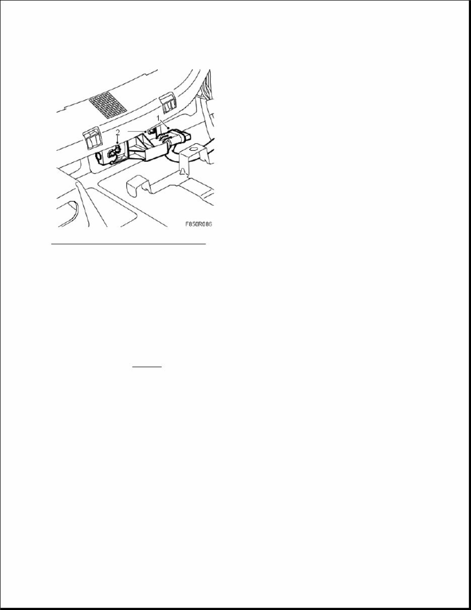
Fig. 102: Illustration For Steps 1 And 2 Courtesy of SAAB-SCANIA OF AMERICA, INC. 2. Fit the side impact sensor by placing the sensor in its position. Pull forward the front part of the sensor. Tighten the screws. Tightening torque 6 Nm (4 lbf ft) 3. Refit the carpet. 4. Fit the B-pillar trim. 5. Fit the front and rear scuff plates. 6. Fit the front seat. See SEATS . 7. Connect the battery. 8. Turn ON the ignition switch and check the airbag system and control module using the diagnostic tool as follows: Connect the diagnostic tool to the data link connector under the dashboard. Delete any diagnostic trouble codes. Turn the ignition OFF and then ON again. Wait at least 1 minute with the ignition on. Check if any fault codes are displayed: If a diagnostic trouble code is shown: Carry out fault diagnosis according to the instructions under respective trouble codes. If a diagnostic trouble code is not shown:
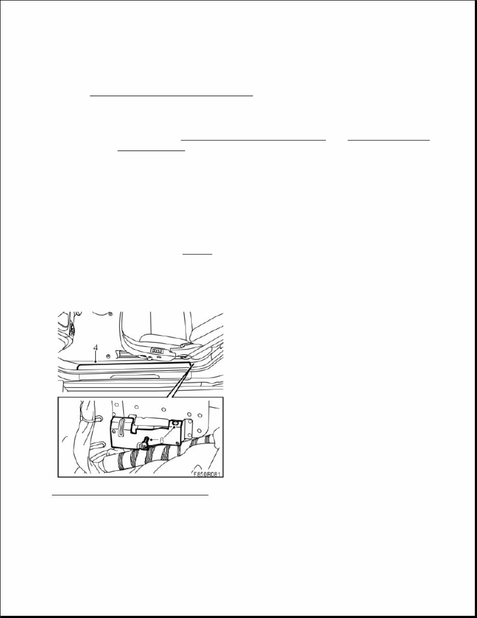
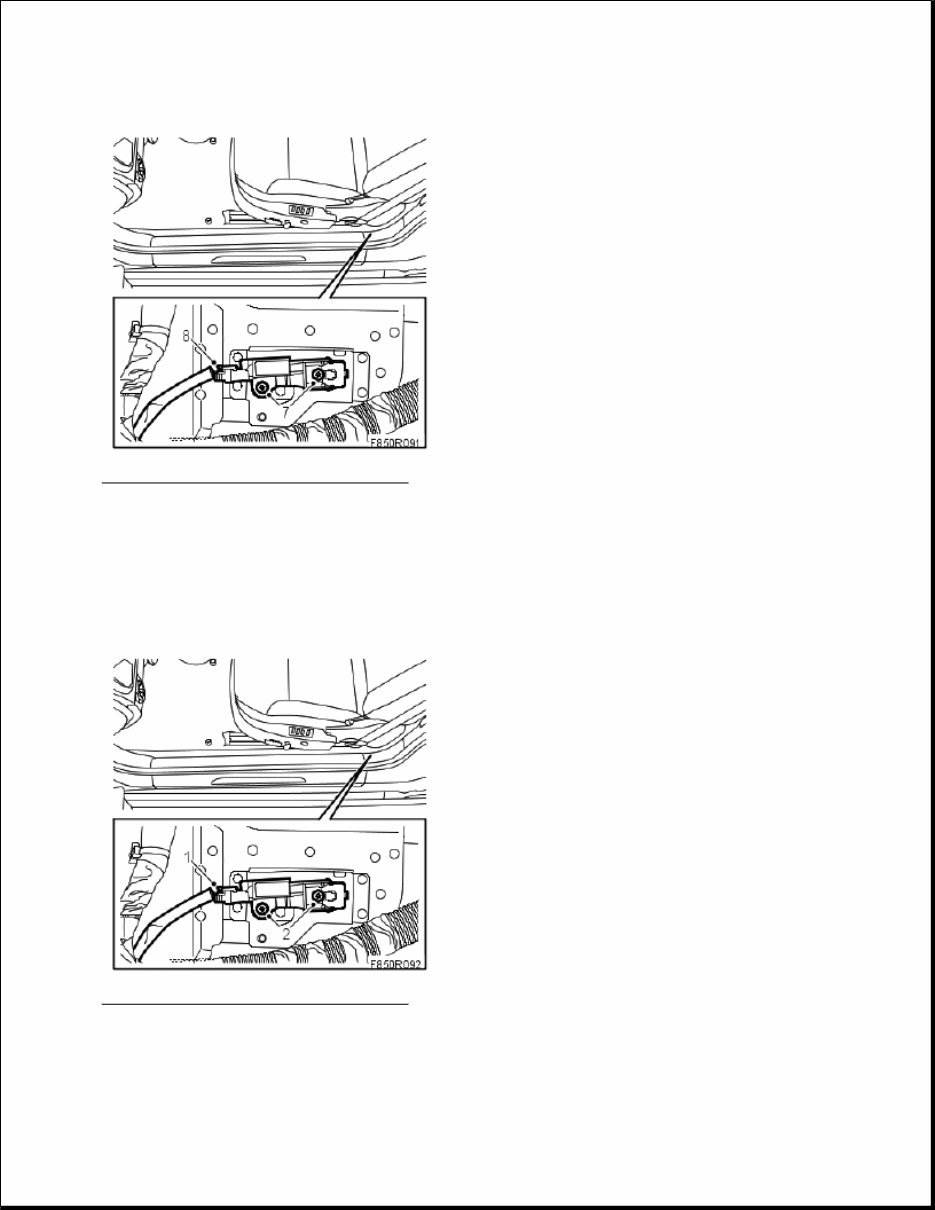
The assembly was successful. Disconnect the diagnostic tool. 9. Carry out Measures after disconnecting the battery . IMPACT SENSOR, SIDE (328D, 328P), CV To remove 1. Remove the rear seat cushion. See SEATS . 2. Turn the ignition key to the LOCK position. 3. Set the seat to its front position. 4. Remove the inner sill trim. Fig. 103: Illustration For Steps 4 And 6 Courtesy of SAAB-SCANIA OF AMERICA, INC. 5. Fold under the carpet. 6. Remove the protective plate. 7. Release the screws a few turns, press the locking clip together on the rear of the side impact sensor. Press WARNING: Read through Safety and handling instructions and Before removing a control module before starting work. WARNING: The battery's ground cable must be removed before the positive cable. Wait for at least 1 minute after disconnecting the battery before beginning any work on the airbag system. Otherwise the airbag may be deployed unintentionally and this can cause fatal/severe personal injuries.
Fig. 104: Illustration For Steps 7 And 8 Courtesy of SAAB-SCANIA OF AMERICA, INC. 8. Remove the connector from the side impact sensor. To fit 1. Attach the connector to the side impact sensor. Fig. 105: Illustration For Steps 1 And 2 Courtesy of SAAB-SCANIA OF AMERICA, INC. 2. Position the sensor and pull the front part forwards. Tighten the screws.
This is the Mitchell On Demand Software (MODS) manual. It is a comprehensive resource used by professional mechanics and DIY enthusiasts alike. The manual contains over 500 pages of service data, technical information, performance data, illustrated diagrams, and much more.
The topics covered in this manual include air conditioning & heat, automatic/manual transmissions, brakes, engine mechanical, engine performance, general information, powertrain, steering & suspension, technical service bulletins, recalls/technical information, wiring diagrams, torque specifications, alignment procedures and specifications, transmission removal and installation, air conditioning service and capacities, transmission servicing procedures, brake servicing procedures, firing orders, engine overhaul and rebuilding, computer diagnostic trouble tree charts, factory maintenance schedules and charts, belt routings with diagrams, timing belt service procedures, computer diagnostic codes, drivability concerns, U-joint and CV-joint service procedures, and more.