


VMR2004_001_00_02A.FM I
SECTION SUBSECTION PAGE
SAFETY NOTICE ................................................................................................................................... III
INTRODUCTION .................................................................................................................................. IV
01 SERVICE TOOLS AND
SERVICE PRODUCTS
01 – Table of contents...................................................................... 01-01-1
02 – Service tools ............................................................................. 01-02-1
03 – Service products....................................................................... 01-03-1
02 MAINTENANCE 01 – Table of contents...................................................................... 02-01-1
02 – Maintenance chart.................................................................... 02-02-1
03 – Maintenance/lubrication ........................................................... 02-03-1
04 – Storage/preseason preparation ................................................ 02-04-1
03 ENGINE 01 – Table of contents...................................................................... 03-01-1
02 – Troubleshooting........................................................................ 03-02-1
03 – Leak test................................................................................... 03-03-1
04 – Removal and installation........................................................... 03-04-1
05 – Cooling system......................................................................... 03-05-1
06 – Magneto system ...................................................................... 03-06-1
07 – Lubrication system ................................................................... 03-07-1
08 – Cylinder and head ..................................................................... 03-08-1
09 – Crankshaft/balancer shaft ......................................................... 03-09-1
10 – Clutch ....................................................................................... 03-10-1
11 – Transmission ............................................................................ 03-11-1
04 FUEL SYSTEM 01 – Table of contents...................................................................... 04-01-1
02 – Fuel circuit ................................................................................ 04-02-1
03 – Carburetor and air intake silencer ............................................. 04-03-1
05 ELECTRICAL 01 – Table of contents...................................................................... 05-01-1
02 – Overview .................................................................................. 05-02-1
03 – Charging system ...................................................................... 05-03-1
04 – Starting system ........................................................................ 05-04-1
05 – Ignition system......................................................................... 05-05-1
06 – Accessories .............................................................................. 05-06-1
06 DRIVE TRAIN 01 – Table of contents...................................................................... 06-01-1
02 – Front drive ................................................................................ 06-02-1
03 – Rear axle .................................................................................. 06-03-1
07 STEERING SYSTEM 01 – Table of contents...................................................................... 07-01-1
02 – Steering system ....................................................................... 07-02-1
08 SUSPENSION 01 – Table of contents...................................................................... 08-01-1
02 – Front suspension ...................................................................... 08-02-1
03 – Rear suspension ....................................................................... 08-03-1
09 BRAKES 01 – Table of contents...................................................................... 09-01-1
02 – Hydraulic brakes ....................................................................... 09-02-1
TABLE OF CONTENTS

II VMR2004_001_00_02A.FM
10 BODY/FRAME 01 – Table of contents ..................................................................... 10-01-1
02 – Body ......................................................................................... 10-02-1
03 – Frame ....................................................................................... 10-03-1
11 TECHNICAL DATA 01 – SI metric information guide...................................................... 11-01-1
02 – Engine and vehicle ................................................................... 11-02-1
12 WIRING DIAGRAMS 01 – Wiring diagrams ....................................................................... 12-01-1
SECTION SUBSECTION PAGE
TABLE OF CONTENTS
IV VMR2004_001_00_02A.FM
INTRODUCTION
This Shop Manual covers the following Bombardier
made 2004 ATVs:
2004 Models
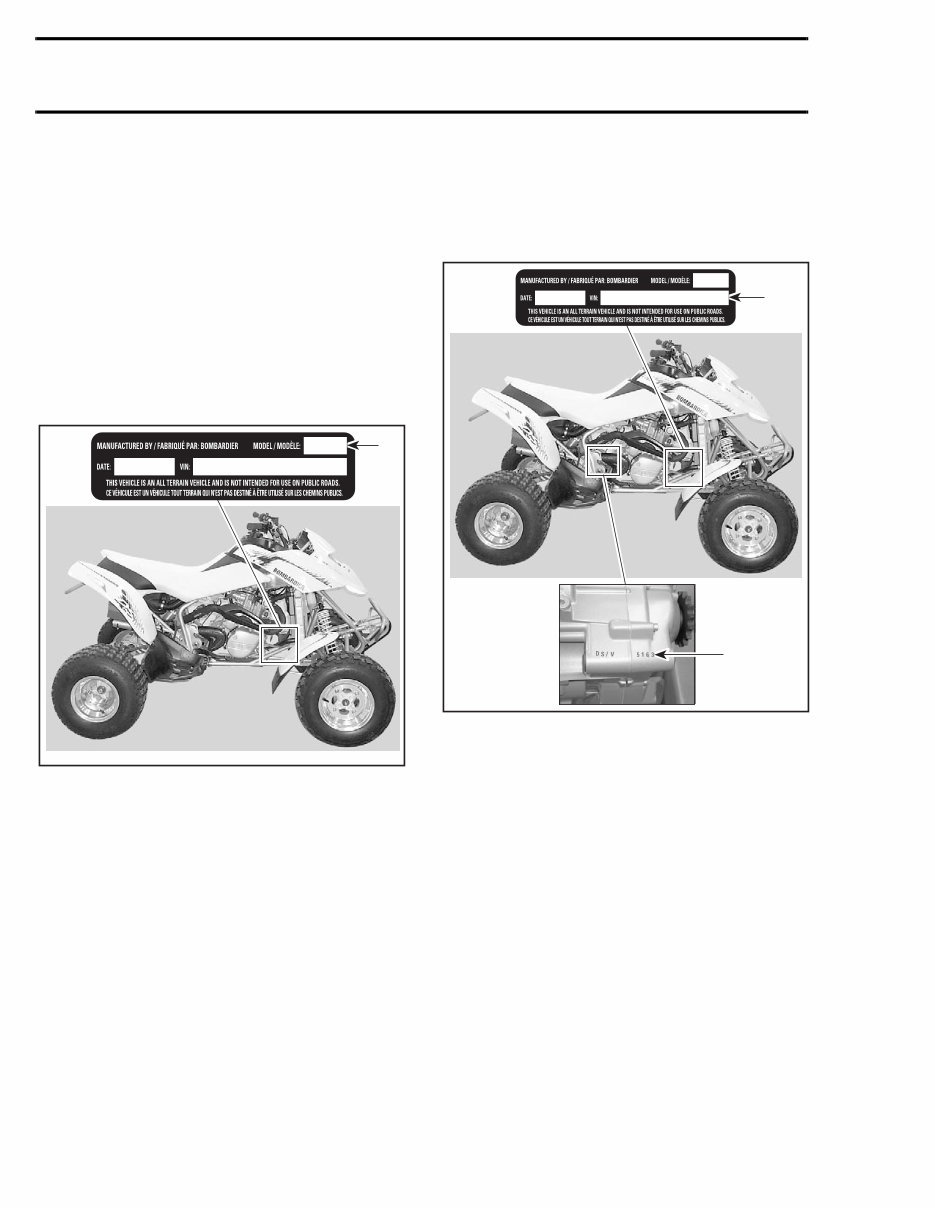
TYPICAL
1. Model number
VEHICLE AND ENGINE SERIAL
NUMBER LOCATION
TYPICAL
1. Vehicle
2. Engine
DS 650
TM
..................................................... 7717
DS 650
TM
Baja.............................................. 7718
DS 650
TM
Baja X .......................................... 7995
DS 650
TM
Intl ............................................... 7719
DS 650
TM
Baja Intl ....................................... 7720
DS 650
TM
Baja X Intl .................................... 7997
INTRODUCTION

VMR2004_001_00_02A.FM V
ARRANGEMENT OF THE
MANUAL
The manual is divided into 12 major sections:
Each section is divided in various subsections, and
again, each subsection has one or more divisions.
LIST OF ABBREVIATIONS USED
IN THIS MANUAL
01 SERVICE TOOLS AND SERVICE PRODUCTS
02 MAINTENANCE
03 ENGINE
04 FUEL SYSTEM
05 ELECTRICAL
06 DRIVE TRAIN
07 STEERING SYSTEM
08 SUSPENSION
09 BRAKES
10 BODY/FRAME
11 TECHNICAL DATA
12 WIRING DIAGRAMS
A ampere
amp ampere
Ah ampere-hour
AC alternate current
BDC bottom dead center
BTDC before top dead center
°C degree Celsius
cm centimeter
cm² square centimeter
cm³ cubic centimeter
DC direct current
°F degree Fahrenheit
fl. oz fluid ounce
ft foot
GRD ground
hal. halogen
I.D. inside diameter
IDI induction discharge ignition
imp. oz imperial ounce
in inch
in² square inch
in³ cubic inch
k kilo (thousand)
kg kilogram
km/h kilometer per hour
kPa kilo pascal
L liter
lb pound
lbf pound (force)
LH left hand
m meter
MAG magneto
Max. maximum
Min. minimum
mL milliliter
mm millimeter
MPH mile per hour
N newton
N.A. not applicable
no. number
00.0 continuity
O.L. overload (open circuit)
O.D. outside diameter
OPT optional
oz ounce
P/N part number
PSI pound per square inch
PTO power take off
RPM revolution per minute
Sp. Gr. specific gravity
TDC top dead center
U.S. oz ounce (United States)
V volt
Vac volt (alternative current)
INTRODUCTION
VI VMR2004_001_00_02A.FM
INTRODUCTION

VMR2004_001_00_02A.FM VII
INTRODUCTION
VIII VMR2004_001_00_02A.FM
GENERAL INFORMATION
The information and component/system descrip-
tions contained in this manual are correct at time
of publication. Bombardier Inc. however, main-
tains a policy of continuous improvement of its
products without imposing upon itself any obliga-
tion to install them on products previously manu-
factured.
Due to late changes, there may be some differences
between the manufactured product and the descrip-
tion and/or specifications in this document.
Bombardier Inc. reserves the right at any time to dis-
continue or change specifications, designs, features,
models or equipment without incurring obligation.
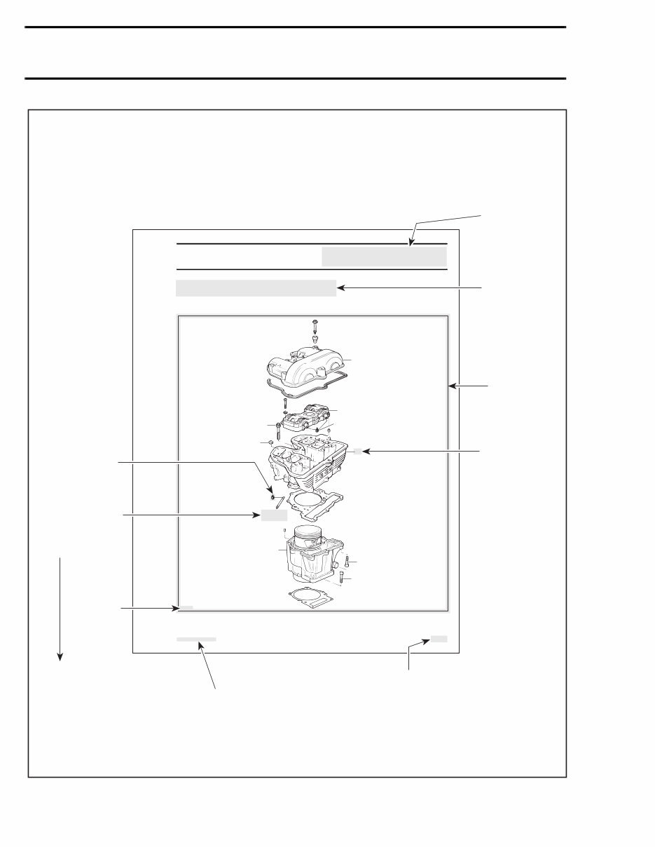
ILLUSTRATIONS AND
PROCEDURES
Illustrations and photos show the typical construc-
tion of the different assemblies and, in all cases,
may not reproduce the full detail or exact shape of
the parts shown, however, they represent parts
that have the same or a similar function.
CAUTION: Most components in the vehicles are
built with parts dimensioned in the metric sys-
tem. Most fasteners are metric and must not be
replaced by customary fasteners or vice- versa.
Mismatched or incorrect fasteners could cause
damage to the vehicle or possible personal injury.
As many of the procedures in this manual are in-
terrelated, we suggest, that before undertaking
any task, you read and thoroughly understand the
entire section or subsection concerning the proce-
dure.
A number of procedures throughout the book re-
quire the use of special tools. Before starting any
procedure, be sure that you have on hand all re-
quired tools, or approved equivalents.
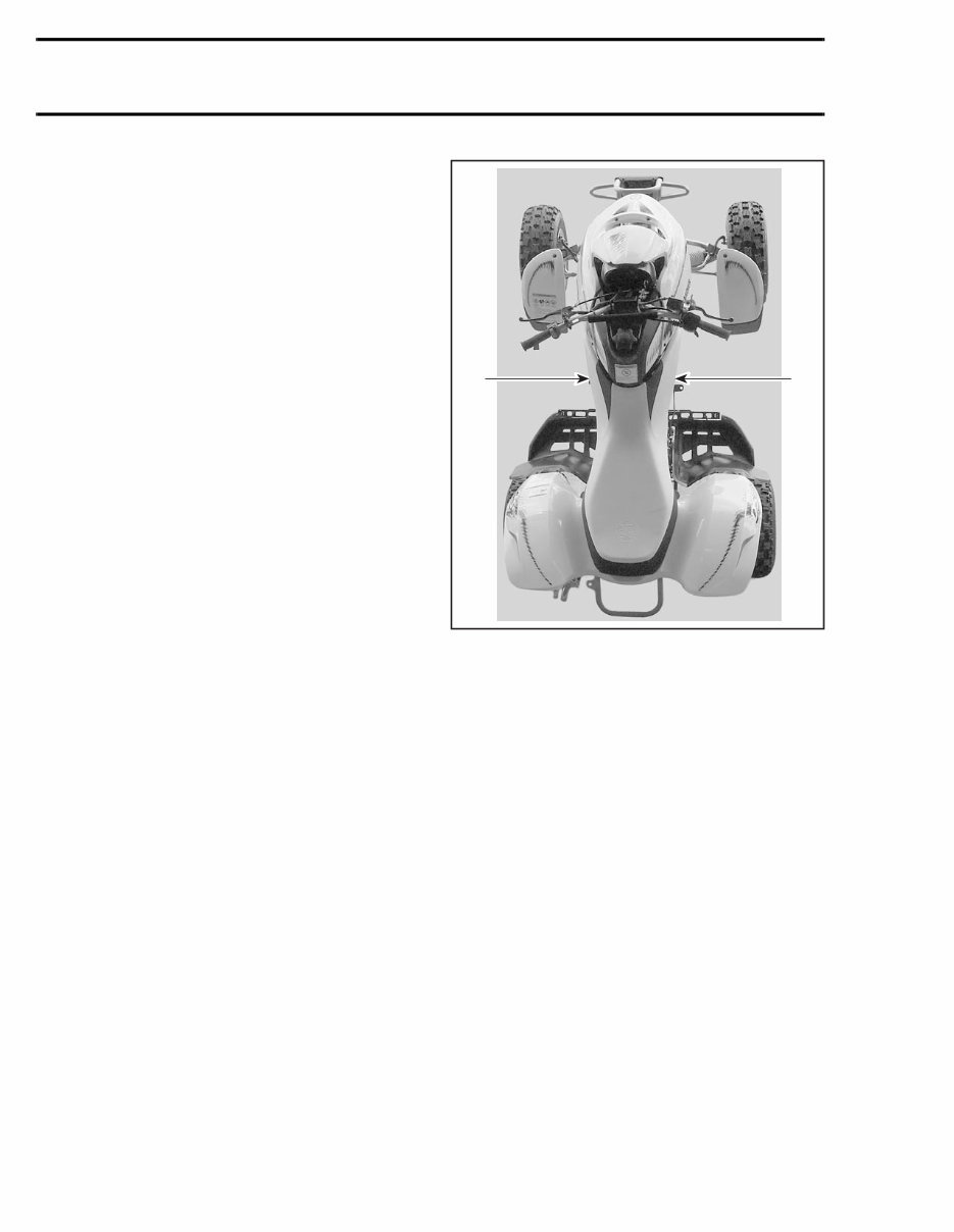
The use of RIGHT and LEFT indications in the text,
always refers to driving position (sitting on the ve-
hicle).
1. Left
2. Right
SELF-LOCKING FASTENERS
PROCEDURE
The following describes the most common appli-
cation procedures when working with self-locking
fasteners.
Use a metal brush or a screwtap to clean the hole
properly then use a solvent (Methyl-Chloride), let
it sit during 30 minutes and wipe off. The solvent
ensures the adhesive works properly.
LOCTITE APPLICATION
PROCEDURE
The following describes the most common appli-
cation procedures when working with Loctite
products.
NOTE: Always use proper strength Loctite prod-
uct as recommended in this Shop Manual.
INTRODUCTION
VMR2004_001_00_02A.FM IX
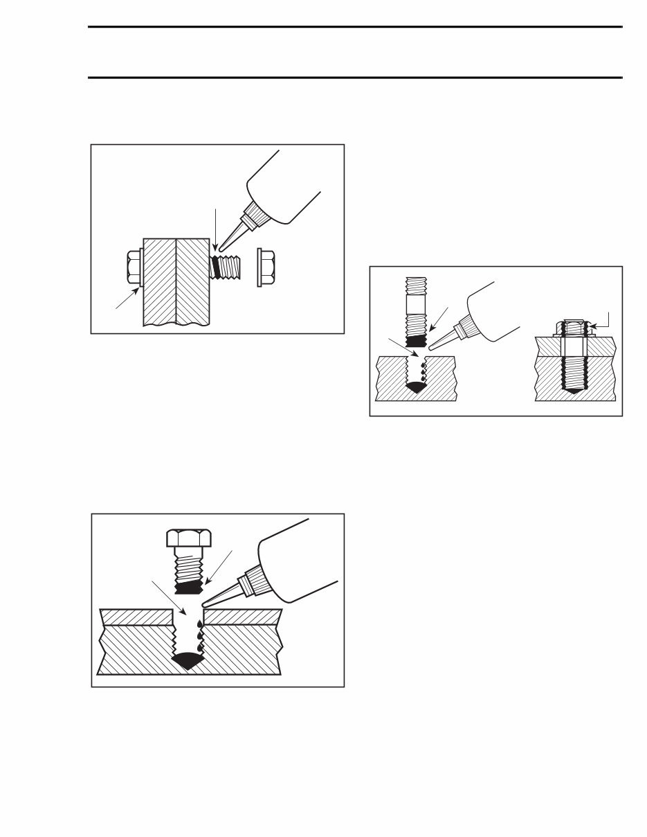
Threadlocker
Uncovered Holes (bolts and nuts)
1. Apply here
2. Do not apply
1. Clean threads (bolt and nut) with solvent.
2. Apply Loctite Primer N (P/N 293 800 041) on
threads and allow to dry.
3. Choose proper strength Loctite threadlocker.
4. Fit bolt in the hole.
5. Apply a few drops of threadlocker at proposed
tightened nut engagement area.
6. Position nut and tighten as required.
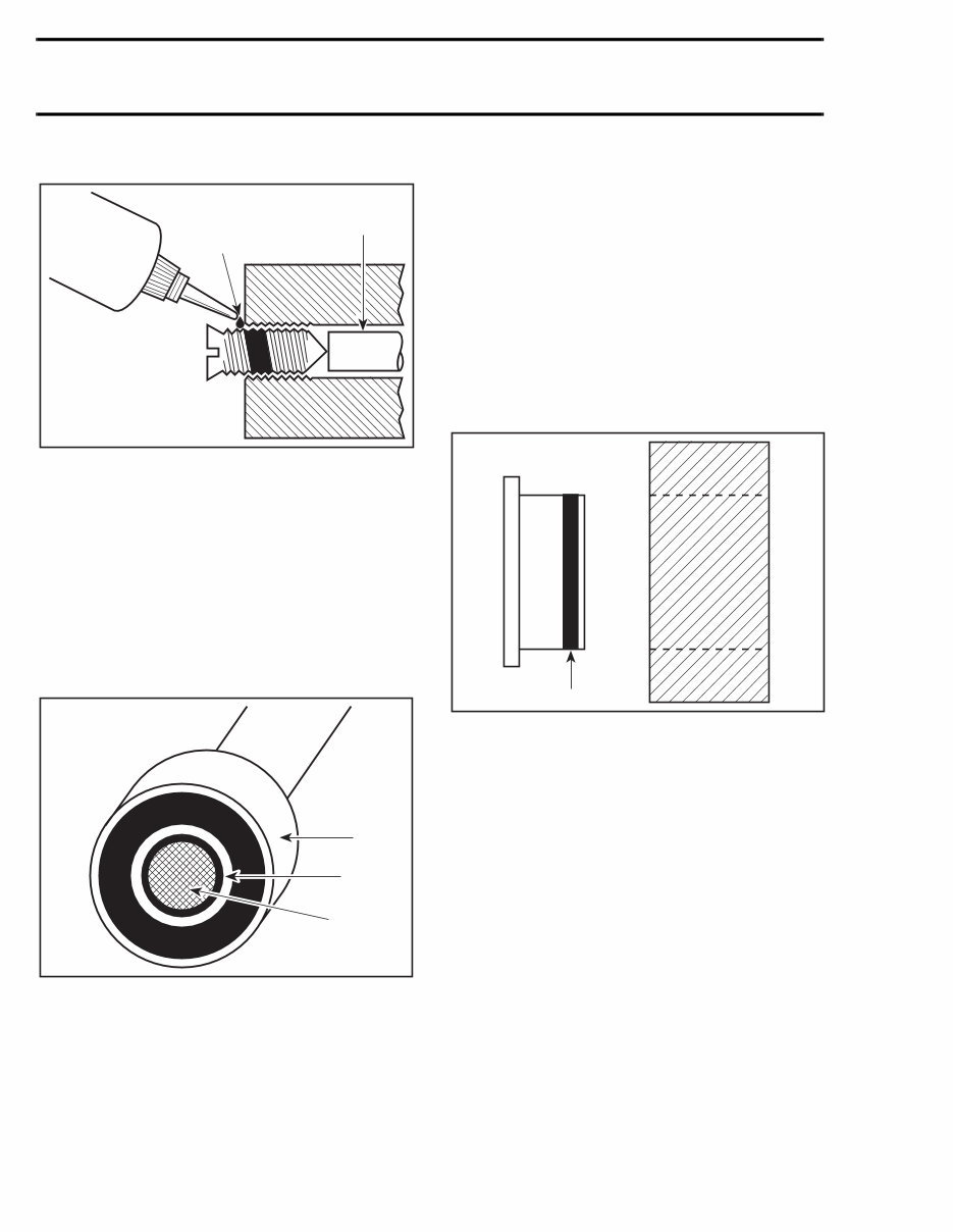
Blind Holes
1. On threads
2. On threads and at the bottom of hole
1. Clean threads (bolt and hole) with solvent.
2. Apply Loctite Primer N (P/N 293 800 041) on
threads (bolt and nut) and allow to dry for 30
seconds.
3. Choose proper strength Loctite threadlocker.
4. Apply several drops along the threaded hole and
at the bottom of the hole.
5. Apply several drops on bolt threads.
6. Tighten as required.
Stud in Blind Holes
1. On threads
2. On threads and in the hole
3. Onto nut threads
1. Clean threads (stud and hole) with solvent.
2. Apply Loctite Primer N (P/N 293 800 041) on
threads and allow to dry.
3. Put several drops of proper strength Loctite
threadlocker on female threads and in hole.
4. Apply several drops of proper strength Loctite
on stud threads.
5. Install stud.
6. Install cover, etc.
7. Apply drops of proper strength Loctite on un-
covered threads.
8. Tighten nuts as required.
A00A3LA
1
2
INTRODUCTION
X VMR2004_001_00_02A.FM
Adjusting Screw
1. Apply here
2. Plunger
1. Adjust screw to proper setting.
2. Apply drops of proper strength Loctite thread-
locker on screw/body contact surfaces.
3. Avoid touching metal with tip of flask.
NOTE: If it is difficult to readjust, heat screw with
a soldering iron (232°C (450°F)).
Mounting on Shaft
Mounting with a Press
1. Bearing
2. Proper strength Loctite
3. Shaft
Standard
1. Clean shaft external part and element internal
part.
2. Apply a strip of proper strength Loctite on shaft
circumference at insert or engagement point.
NOTE: Retaining compound is always forced out
when applied on shaft.
3. DO NOT use anti-seize Loctite or any similar
product.
4. No curing period is required.
Mounting in Tandem
1. Apply retaining compound on internal element
bore.
2. Continue to assemble as shown above.
Case-In Components
Metallic Gaskets
1. Proper strength Loctite
1. Clean inner housing diameter and outer gasket
diameter.
2. Spray housing and gasket with Loctite Primer N
(P/N 293 800 041).
3. Apply a strip of proper strength Loctite on lead-
ing edge of outer metallic gasket diameter.
NOTE: Any Loctite product can be used here. A
low strength liquid is recommended as normal
strength and gap are required.
4. Install according to standard procedure.
5. Wipe off surplus.
6. Allow it to cure for 30 minutes.
NOTE: Normally used on worn-out housings to
prevent leaking or sliding.
It is generally not necessary to remove gasket
compound applied on outer gasket diameter.
A00A3UA
1
2
3
A00A3VA 1
INTRODUCTION
VMR2004_001_00_02A.FM XI
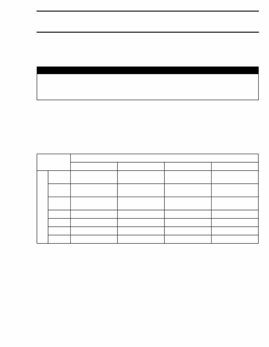
TIGHTENING TORQUES
Tighten fasteners to torque mentioned in exploded views and text. When they are not specified refer to
following tables. The tables also give the metric conversion.
In order to avoid a poor assembling, tighten screws and bolts in accordance with the following procedure:
1. Manually screw all screws, bolts and/or nuts.
2. Apply the half of the recommended torque value.
CAUTION: Be sure to use the proper tightening torque for the proper strength grade.
NOTE: When possible, always apply torque on the nut.
3. Torque at the recommended torque value.
NOTE: Always torque screws, bolts and/or nuts in a criss-cross sequence.
WARNING
Torque wrench tightening specifications must be strictly adhered to.
Locking devices (ex.: locking tab, elastic stop nut, self-locking fasteners, etc.) must be installed or
replaced with new ones where specified. If the efficiency of a locking device is impaired, it must
be renewed.
TIGHTENING
TORQUE
STRENGTH GRADE
GRADE 5.8 GRADE 8.8 GRADE 10.9 GRADE 12.9
DIMENSION
M4
1.5 to 2 N•m
(13 to 18 lbf•in)
2.5 to 3 N•m
(22 to 27 lbf•in)
3.5 to 4 N•m
(31 to 35 lbf•in)
4 to 5 N•m
(35 to 44 lbf•in)
M5
3 to 3.5 N•m
(27 to 31 lbf•in)
4.5 to 5.5 N•m
(40 to 47 lbf•in)
7 to 8.5 N•m
(62 to 75 lbf•in)
8 to 10 N•m
(71 to 89 lbf•in)
M6
6.5 to 8.5 N•m
(58 to 75 lbf•in)
8 to 12 N•m
(71 to 106 lbf•in)
10.5 to 15 N•m
(93 to 133 lbf•in)
16 N•m (12 lbf•ft)
M8 15 N•m (11 lbf•ft) 24.5 N•m (18 lbf•ft) 31.5 N•m (23 lbf•ft) 40 N•m (30 lbf•ft)
M10 29 N•m (21 lbf•ft) 48 N•m (35 lbf•ft) 61 N•m (45 lbf•ft) 72.5 N•m (53 lbf•ft)
M12 52 N•m (38 lbf•ft) 85 N•m (63 lbf•ft) 105 N•m (77 lbf•ft) 127.5 N•m (94 lbf•ft)
M14 85 N•m (63 lbf•ft) 135 N•m (100 lbf•ft) 170 N•m (125 lbf•ft) 200 N•m (148 lbf•ft)
INTRODUCTION
You're Reading a Preview
What's Included?
Fast Download Speeds
Online & Offline Access
Access PDF Contents & Bookmarks
Full Search Facility
Print one or all pages of your manual
$31.99
2004 Bombardier DS650 DS 650 Baja Service & Repair Manual
Viewed 41 Times Today

What's Included?
Fast Download Speeds
Online & Offline Access
Access PDF Contents & Bookmarks
Full Search Facility
Print one or all pages of your manual
$31.99

Secure transaction
What's Included?
Fast Download Speeds
Online & Offline Access
Access PDF Contents & Bookmarks
Full Search Facility
Print one or all pages of your manual
Description
Get your hands on the comprehensive repair manual for the 2004 Bombardier DS650 ATV, including the Baja and Baja X models. This manual covers everything from complete tear down and rebuild to pictures and part diagrams, torque specs, maintenance, troubleshooting, and more, all within its 245 pages.
With clickable chapters and a search function, finding the information you need is a breeze. Plus, there are no restrictions on printing or saving/burning to disc.
- Complete tear down and rebuild
- Pictures and part diagrams
- Torque specs
- Maintenance procedures
- Troubleshooting guidance
- Clickable chapters
- Searchable content
- No printing or saving restrictions


